
Finfet with multiple dislocation planes and method for forming same

A dislocation, semiconductor technology, used in semiconductor devices, electrical components, transistors, etc.

Active Publication Date: 2019-07-19
TAIWAN SEMICON MFG CO LTD
View PDF4 Cites 0 Cited by
  • Summary
  • Abstract
  • Description
  • Claims
  • Application Information

AI Technical Summary

Problems solved by technology

Short channel effects of conventional planar transistors have been reduced

Method used


Image

  • Finfet with multiple dislocation planes and method for forming same
  • Finfet with multiple dislocation planes and method for forming same
  • Finfet with multiple dislocation planes and method for forming same

Examples


Embodiment Construction

[0047] The following disclosure provides a number of different embodiments or examples for implementing different features of the presented subject matter. Specific examples of components and arrangements are described below to simplify the present disclosure. Of course, these are only examples and are not intended to limit the invention. For example, in the following description, forming a first component over or on a second component may include embodiments in which the first component and the second component are in direct contact, and may include additional components formed between the first component and the second component An embodiment such that the first part and the second part are not in direct contact. Additionally, the present invention may repeat reference symbols and / or characters in multiple instances. This repetition is for the purposes of simplicity and clarity, and does not in itself indicate a relationship between the various embodiments and / or configura...


PUM


Abstract

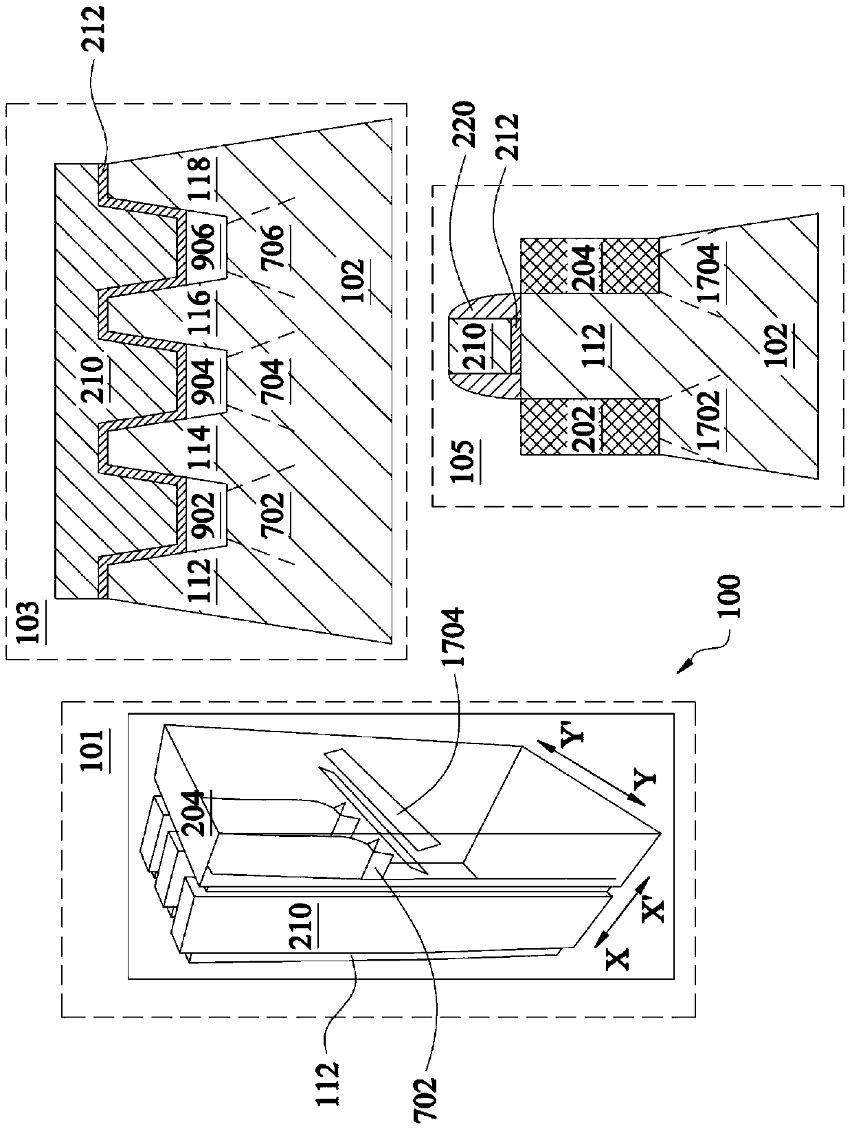
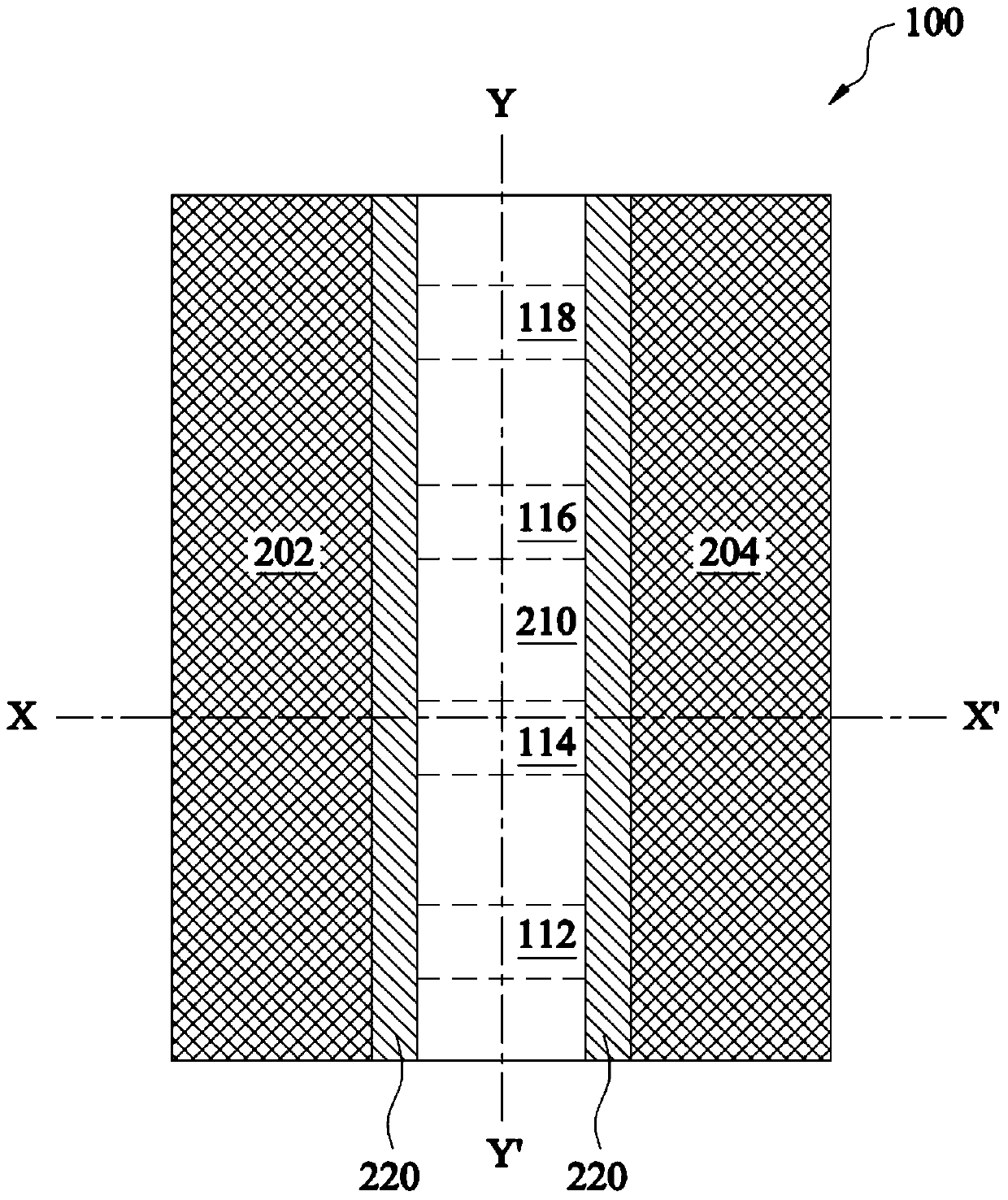
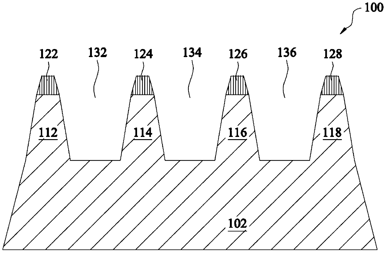
A device comprises a first semiconductor fin over a substrate, a second semiconductor fin over the substrate, wherein the first semiconductor fin and the second semiconductor fin are separated by a first isolation region, a first drain / source region coupled to the first semiconductor fin and the second semiconductor fin and a first dislocation plane underlying the first isolation region, wherein the first dislocation plane extends in a first direction in parallel with a longitudinal axis of the first semiconductor fin.

Description

technical field [0001] The present invention relates generally to the field of semiconductors, and more particularly to FinFET transistors. Background technique [0002] The semiconductor industry has experienced rapid development due to the ever-increasing integration density of various electronic components (eg, transistors, diodes, resistors, capacitors, etc.). For the most part, this increase in integration density stems from repeated reductions in minimum feature size, allowing more components to be integrated within a given area. However, smaller feature sizes can result in more leakage current. With the recent increase in demand for smaller electronic devices, it is necessary to reduce the leakage current of semiconductor devices. [0003] In a complementary metal-oxide-semiconductor (CMOS) field-effect transistor (FET), the active region consists of a drain, a source, a channel region connected between the drain and source, and the top of the channel to control the...

Claims


Application Information

Patent Timeline
Patent Type & Authority Patents(China)
IPC IPC(8): H01L29/78H01L29/32H01L21/336H01L27/092
CPCH01L29/7847H01L21/26506H01L21/324H01L21/76224H01L21/823418H01L21/823431H01L21/823481H01L21/845H01L27/0886H01L27/1211H01L29/0653H01L29/66545H01L29/66636H01L29/66795H01L29/7848H01L29/785
Inventor 黄志翔林大文
Owner TAIWAN SEMICON MFG CO LTD
Learn More