
Ventilating structure and method for distributing flow of internal and external cooling medium based on loss ratio

A technology of cooling medium and external ventilation, applied in the direction of casing/cover/support, electrical components, electromechanical devices, etc., can solve the problems of unreasonable air circulation distribution, lack of cooling effect, etc., to enhance heat exchange capacity, The effect of reducing the radial temperature difference and enhancing the heat dissipation capacity

Inactive Publication Date: 2016-07-06
HARBIN UNIV OF SCI & TECH
View PDF5 Cites 2 Cited by
  • Summary
  • Abstract
  • Description
  • Claims
  • Application Information

AI Technical Summary

Problems solved by technology

[0005] The purpose of the present invention is to solve the problem that the internal components of the motor cannot obtain the proper cooling effect due to the unreasonable distribution of air circulation in the common motor ventilation structure, and provide a ventilation structure and method that distributes the flow of internal and external cooling media according to the loss ratio. Reasonable ventilation mode can indirectly improve the operating performance and power density of the motor, and improve the service life of each component

Method used


Image

  • Ventilating structure and method for distributing flow of internal and external cooling medium based on loss ratio
  • Ventilating structure and method for distributing flow of internal and external cooling medium based on loss ratio
  • Ventilating structure and method for distributing flow of internal and external cooling medium based on loss ratio

Examples


Embodiment Construction

[0025] The present invention will be further described below in conjunction with the embodiments and with reference to the accompanying drawings.

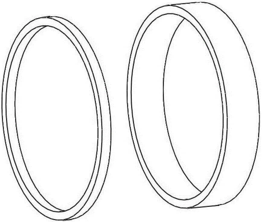
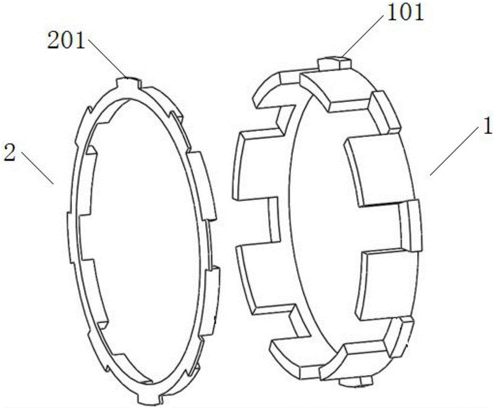
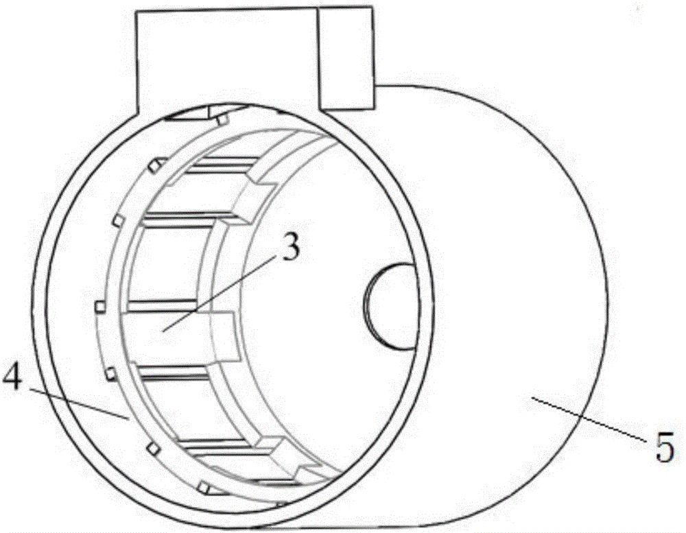
[0026] See figure 1 . figure 1 It is a structural schematic diagram of the internal and external air path baffles of the original motor. The present invention will figure 1 The common internal and external air duct baffle shown in the figure is based on the characteristics of the ventilation ditch of the cabinet, and combined with the distribution of internal and external air ducts, its structure is optimized into figure 2 As shown in the structure, it is placed at both ends of the air duct formed by the stator in the casing. For the external air duct, the drive end enters the air, and the non-drive end outputs the air. Most of the motors have external air ducts on the casing to cool the stator part. This solution allocates half of the chamber of the external air ducts to the internal fluid, which can optimize the cooling capa...


PUM


Abstract

The invention discloses a ventilating structure and a method for distributing flow of internal and external cooling medium based on loss ratio. A novel flowing path for a motor internal cooling medium is designed. The problem of relatively high temperature rise distribution difference of a stator and a rotor caused by unbalanced air ventilation distribution of the original ventilating structure is solved by the ventilating structure provided by the invention; the duty cycle of the internal and external ventilating ducts can be determined according to the ratio of the stator loss in the total loss; on the basis of a common ventilating baffle structure, a baffle is improved; a part of the original external ventilating duct is adopted as the flowing path for the internal cooling medium; the ventilating ducts filled by different cooling mediums are distributed at intervals, so that the internal air can be cooled by the external air; the matching between the baffle and a machine case along the width is adjusted only according to the stator and rotor loss ratio, and the effective heat exchange between a primary circuit and a secondary circuit is realized; balanced cooling effect distribution for the stator part and the rotor part can be realized as well; and therefore, the overall temperature rise distribution condition of the motor is perfected.

Description

technical field [0001] The invention relates to a ventilation structure and method of a motor, in particular to an exchange ventilation structure and method of a motor, and belongs to the technical field of motors. Background technique [0002] The heat transfer inside the motor is a process that is difficult to control. As the requirements for the motor capacity continue to increase, the increase in unit loss will lead to an increase in temperature. When the temperature rise is too high, it will greatly affect the reliability and life of each component. influences. [0003] Since the ratio of the stator and rotor losses to the total loss of different types of motors is different, the flow rate of the cooling medium in each part should be reasonably distributed according to the ratio of loss and heat generation. [0004] There is a certain temperature rise gap between the stator part and the rotor part. Due to the temperature transfer from high temperature to low temperatur...

Claims


Application Information

Patent Timeline
Patent Type & Authority Applications(China)
IPC IPC(8): H02K5/20
CPCH02K5/20H02K2205/09
Inventor 丁树业李珊珊陈景易
Owner HARBIN UNIV OF SCI & TECH
Learn More