Steam-water separation corrugated plate and separation device

A steam-water separator and a technology for steam-water separation, which are applied in separation methods, dispersed particle separation, chemical instruments and methods, etc., can solve the problem of difficult processing and ensure the manufacturing accuracy of corrugated plates, the separation efficiency cannot meet the design requirements, and the separator equipment is bulky. and other problems, to achieve the effect of reducing secondary carry, increasing the effective flow area, and improving the separation efficiency

Active Publication Date: 2016-07-13
SHANGHAI POWER EQUIP RES INST
View PDF5 Cites 8 Cited by
  • Summary
  • Abstract
  • Description
  • Claims
  • Application Information

AI Technical Summary

Problems solved by technology

[0003] Nuclear power plant evaporator dryers and steam-water separation reheaters currently use single-hook and double-hook structure corrugated separation plates, which have the following problems: 1. The critical flow rate of the separator is low; 2. The separator equipment is bulky and expensive; 3. The separation The efficiency cannot meet the design requirements under the condition of large flow and high humidity; 4. The hook parts need to be processed separately and then welded. The structure is complicated, and it is not easy to process and ensure the manufacturing accuracy of corrugated plates.

Method used


Image

  • Steam-water separation corrugated plate and separation device
  • Steam-water separation corrugated plate and separation device
  • Steam-water separation corrugated plate and separation device

Examples


Embodiment 1

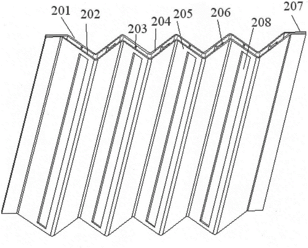
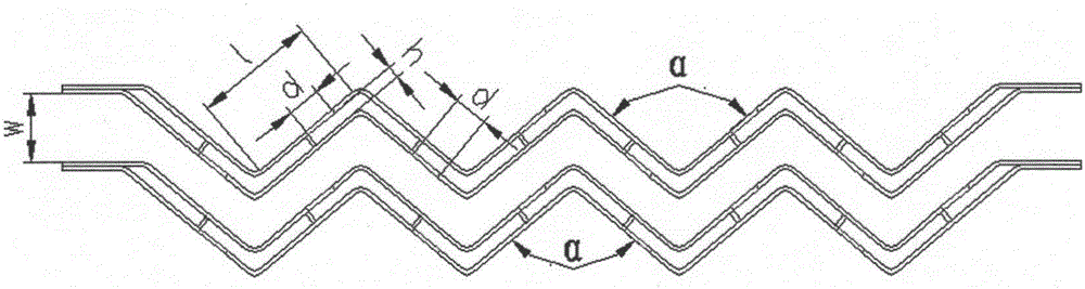
[0025] figure 1 and figure 2 The three-dimensional and planar structural diagrams of the steam-water separation corrugated plate provided in this embodiment are respectively, and the steam-water separation corrugated plate is composed of two hookless corrugated plate combination plates 201, 202, and the middle of the two hookless corrugated plate combination plates 201, 202 The corrugated sections have the same profile and are arranged in parallel to ensure that the gap between the plates remains unchanged, and the corrugated section in the middle is welded and fixed by the connecting plate 203, and the straight plate sections 207 at the two ends of the two hookless corrugated plate composite plates 201 and 202 are partially overlapped and connected. Fixed to form a double-layer hollow plate structure.

[0026] A hydrophobic channel 206 is formed in the hollow between the two hookless corrugated board composite boards 201 and 202 . Drain outlet 208 is set on the windward si...

Embodiment 2

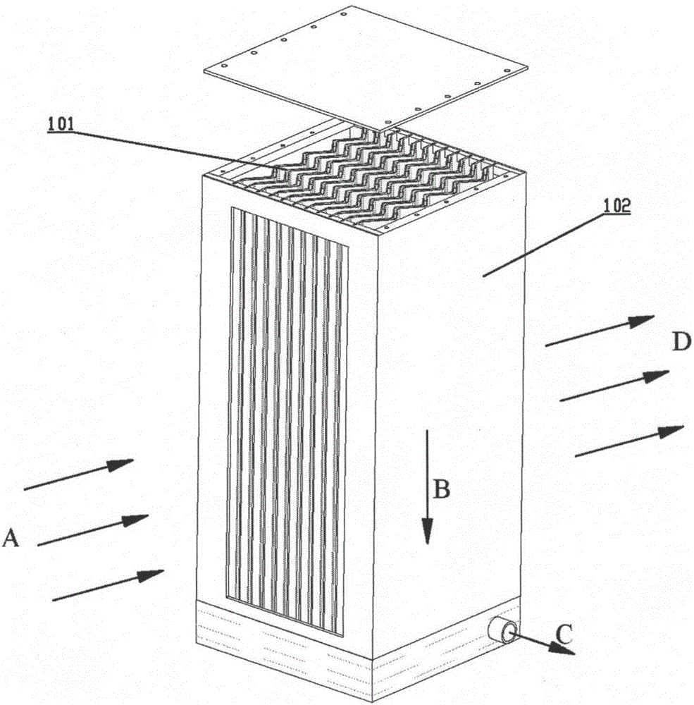
[0034] image 3 The structure schematic diagram of the corrugated plate steam-water separator provided in this embodiment, the corrugated plate steam-water separator includes a housing 102, and several steam-water separating corrugated plates 101 provided in Embodiment 1 are arranged in the housing 102 .

[0035] combine Figure 4 , a number of steam-water separation corrugated plates 101 are equally spaced and parallel arranged in the housing 102, and steam-water separation channels are formed between adjacent steam-water separation corrugated plates 101, Figure 4 The middle arrow indicates the air flow direction.

[0036] combine Figure 5 , the housing 102 consists of a cover plate 301, a distance plate 302, a sealing baffle 303, a windshield 304, a corrugated plate support plate and a hydrophobic buffer plate 305, a hydrophobic groove 306, a cover fixing strip 307, a housing side plate 308 and Drainage pipe 309 is formed, sealing baffle 303 and windshield 304 jointly f...


PUM

PropertyMeasurementUnit
angleaaaaaaaaaa

Abstract

The invention provides a steam-water separation corrugated plate, comprising two crook-free corrugated plates.Middle corrugated segments of the two crook-free corrugated plates are connected through a connecting plate, straight segments at two ends of a combination of the two crook-free corrugated plates are tightly fixed side by side, and a double-layer hollow plate structure is formed; a drain passage forms in the hollow between the two crook-free corrugated plates, and the double-layer hollow plate structure is provided with a drain port.The invention also provides a corrugated plate steam-water separation device.The corrugated plate steam-water separation device is compact in structure and easy to assemble, special crooked drain channel part is not required any more, a flow field in a passage of the separation device is smoother, and resistance coefficient of the passage of the corrugated plates is reduced; manufacture precision of the corrugated plates is improved, and production cost is reduced; with the long drain passage, effective pass area of a drain channel is enlarged, and the ability of the corrugated plate separation device to drain water is improved; the corrugated plate steam-water separation device is useful in separating water particles in steam / water or air-water mixed medium.

Description

technical field [0001] The invention relates to the technical field of steam-water separation, in particular to a steam-water separation corrugated plate and a separator, which can be applied to liquid droplet separation in steam-water and air-water mixed media. Background technique [0002] During the operation of the nuclear power plant system, the requirements for steam dryness are relatively high. In order to obtain higher-quality steam, the nuclear power plant has installed a steam-water separation dryer at the outlet of the steam generator in the primary circuit, and a steam-water separation reheater (MSR) between the high and low pressure cylinders of the secondary circuit steam turbine system to improve the economy of power generation and reduce The occurrence of hazards such as radioactive radiation risk, water erosion of turbine low-pressure cylinder blades, and salt accumulation in pipeline valves. [0003] Nuclear power plant evaporator dryers and steam-water se...

Claims


Application Information

Patent Timeline
Patent Type & Authority Applications(China)
IPC IPC(8): B01D45/08
CPCB01D45/08
Inventor 黎福斌李亚洲周江涛孙海民万鹏
Owner SHANGHAI POWER EQUIP RES INST
Why Eureka
Try Eureka