Steady flow compensation system of water supply equipment

A technology for steady flow compensation and water supply equipment, which is applied to the configuration of water supply pipeline systems, main water supply pipelines, and water supply pools. The effect of stopping and extending the holding time

Inactive Publication Date: 2016-07-13
WUXI KANGYU WATER TREATMENT EQUIP
View PDF5 Cites 2 Cited by
  • Summary
  • Abstract
  • Description
  • Claims
  • Application Information

AI Technical Summary

Problems solved by technology

[0004] ①In the actual production process, the high-pressure chamber and air-pressure chamber inside the tank are in accordance with the production standards of pressure vessels, which is difficult to manufacture and the process is cumbersome;
[0005] ② Once the high-pressure chamber and air-pressure chamber in the tank leak due to welding or corrosion problems, it is difficult to repair and bring serious hidden dangers to the overall operation of the equipment;
[0006] ③Equipment with a single-tank multi-chamber structure, but when the water supply of the municipal pipe network is insufficient, although the high-pressure chamber of the equipment can compensate a certain amount of water, it cannot meet the demand for a larger compensation amount, and the relative compensation amount is relatively small
[0008] 1. Although the three-tank structure design has increased a certain amount of compensation, for a system with a large flow rate, the compensation amount is still relatively small for the three-tank design, and it is difficult to meet greater design requirements;
[0009] 2. The number of tanks in the three-tank design is fixed, which has limitations, and the adjustment range of the compensation flow is small. The compensation amount can only be increased by changing the size of the tank, but it will cause inconvenience in installation and transportation due to the increase of the tank

Method used


Image

  • Steady flow compensation system of water supply equipment

Examples


Embodiment Construction

[0023] The present invention will be further described below in conjunction with accompanying drawing.

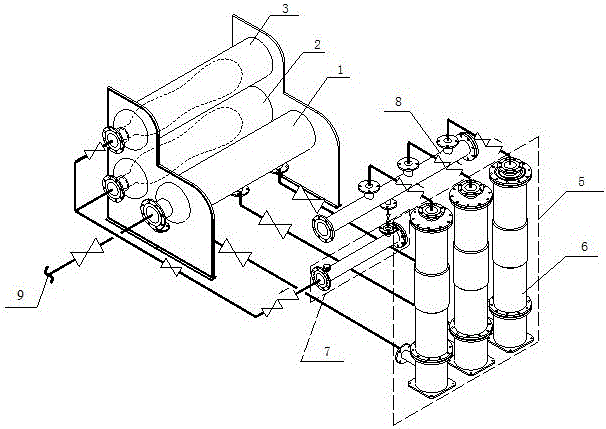
[0024] The water supply equipment steady flow compensation system provided by the present invention is as follows: figure 1 As shown, it includes a three-tank structure, a full frequency conversion booster unit 5 and an energy storage booster unit 7. The three-tank structure is a sub-tank integrated structure composed of a low-pressure tank 1, a high-pressure tank 2 and an ultra-high pressure tank 3. , the low-pressure tank 1 is connected between the municipal pipe network inlet pipe 9 and the full frequency conversion booster unit 5, the high-pressure tank 2 is connected with the low-pressure tank 1 through a countercurrent compensator; the high-pressure tank 2 and the ultra-high pressure tank 3 are equipped with The food-grade air bag 4 is pre-charged with a certain pressure of gas (the gas can be an inert gas) between the inner wall of the tank and the air bag 4, and the...


PUM


Abstract

The invention provides a steady flow compensation system of water supply equipment. The steady flow compensation system comprises a three-tank structure, an all-variable speed pressurization unit and an energy storage and pressurization unit; the three-tank structure is a tank-split type integrated structure composed of a low pressure tank, a high pressure tank and an ultrahigh pressure tank, the low pressure tank is connected between a water inlet pipe of a municipal pipe network and the all-variable speed pressurization unit, and the high pressure tank is connected with the low pressure tank through a countercurrent compensator; the high pressure tank and the low pressure tank are each internally provided with a food-grade air bag, and the two air bags are connected through the energy storage and pressurization unit. The all-variable speed pressurization unit and the energy storage and pressurization unit are connected to a user pipe network through a water outlet pipe. According to the steady flow compensation system, a traditional single-tank multi-cavity structure is omitted, multiple tanks are integrated, the size is reduced by nearly 2/3 compared with a traditional single tank, the problems that production and manufacturing difficulty is high, transport is inconvenient, and the working procedure is complex are solved, maintenance is convenient, and safety is high.

Description

technical field [0001] The invention relates to the technical field of energy saving and environmental protection, in particular to a steady flow compensation system for water supply equipment. Background technique [0002] As the foundation of urban survival and development, the service quality of water supply system is directly related to people's daily life. In recent years, with the advancement of the national informatization strategy, the informatization development of the water supply industry has gone through two stages of specialization and informatization, realizing the sharing, publishing and visualization of water supply information, and effectively improving the informatization management and service of the water supply industry Level. [0003] In the existing water supply equipment, the design of the tank body is mostly a single-tank multi-chamber structure. The conventional design has two or three chambers, namely a constant pressure chamber and a high pressur...

Claims


Application Information

Patent Timeline
Patent Type & Authority Applications(China)
IPC IPC(8): E03B11/00E03B7/07
CPCE03B11/00E03B7/078
Inventor 蒋介中姚介新王奇曹彬
Owner WUXI KANGYU WATER TREATMENT EQUIP
Why Eureka
Try Eureka