Spherical compressor

A spherical compressor, hemispherical technology, applied in the direction of mechanical equipment, machine/engine, swing piston machinery, etc., can solve the problems of increasing manufacturing and operating costs, spherical compressor stuck, piston rotation, etc., to achieve a small number of parts , simple structure and low machining accuracy

Active Publication Date: 2016-07-13
深圳市球形动力科技有限公司
View PDF9 Cites 12 Cited by
  • Summary
  • Abstract
  • Description
  • Claims
  • Application Information

AI Technical Summary

Problems solved by technology

[0003] Since the rotation of the piston of the existing spherical compressor is powered by the eccentric main shaft, when the main shaft rotates until the axis of the turntable coincides with the axis of the piston, the resultant force of the main shaft on the turntable intersects the axes of the piston and the turntable perpendicularly, causing the piston to rotate around the axis of the piston The torque is zero, and the piston cannot be rotated, causing the mechanism to stick, which is the dead point of the movement of the mechanism
The patent number is 201410100390.X, and the patent name is "A Spherical Compressor Rotor Anti-Seize Mechanism". The Chinese patent was invented to solve the problem of the dead point position of the spherical compressor being stuck, specifically adding a pin seat to the turntable shaft. , the pin seat is provided with a guide sleeve, and a concave slideway is set on the spherical surface of the cylinder seat or the lower spherical surface of the cylinder body. The concave slideway is distributed during the rotation of the turntable. On the sliding track of the spherical surface; when the torque of the turntable's rotation is zero, when the spindle drives the turntable, the contact force generated by the guide sleeve and the concave slideway can still keep the turntable moving, so that the turntable is not easy to get stuck, fundamentally It solves the dead point problem of the movement of the spherical compressor mechanism, but the concave slideway needs high precision to ensure the good cooperation between the guide sleeve and the concave slideway, and a cooling mechanism needs to be set during the movement of the anti-seize mechanism to prevent the guide sleeve from contacting with the concave slideway. Concave slideway friction generates heat, increasing manufacturing and operating costs

Method used


Image

  • Spherical compressor
  • Spherical compressor
  • Spherical compressor

Examples


Embodiment Construction

[0051] One, the first embodiment:

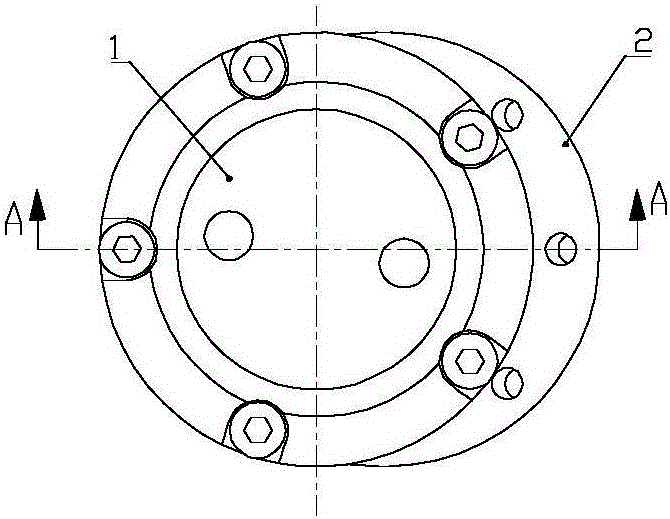
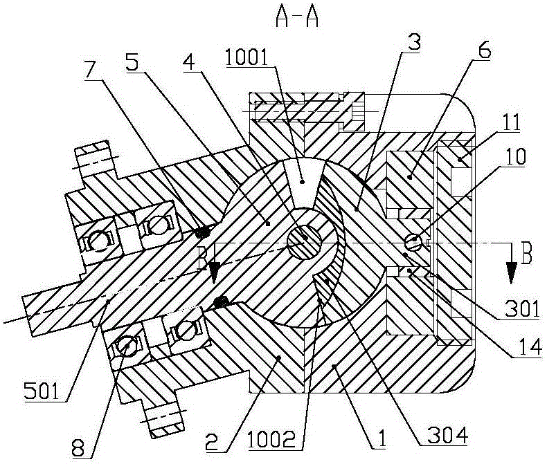
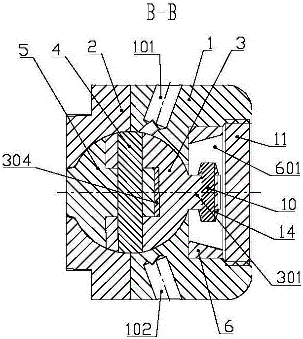
[0052] Figure 1 to Figure 13 Shown is the accompanying drawing of the first embodiment of the patent, as Figure 1 to Figure 8 As shown, the spherical compressor described in this patent includes a cylinder head 1, a cylinder body 2, a piston 3, a center pin 4, a turntable 5, etc., the cylinder body 2 and the cylinder head 1 have a hemispherical inner cavity, and the cylinder body 2 and the cylinder head 1 The casing of a spherical compressor with a spherical inner cavity is formed by screw fixing connection; an intake channel 103, an exhaust channel 104 and a piston shaft hole 105 are arranged on the inner spherical surface of the cylinder head 1; Through the turntable shaft hole 201 outside the cylinder, one side of the turntable shaft hole 201 is connected to the spherical inner cavity, and the other side is provided with a bearing seat hole, which is coaxial with the turntable shaft hole 201; the piston shaft hole 105 and the turntable...


PUM


Abstract

The invention discloses a spherical compressor.A cylinder body (2) and a cylinder cover (1) are combined to form a spherical inner cavity, and a slide groove swing mechanism is arranged between a piston shaft (301) and a piston shaft hole (105) or between a rotating plate shaft (501) and a rotating plate shaft hole (201).The rotating plate shaft (501) is driven to rotate to enable a piston (3) to swing relative to the axis of the piston shaft hole (105) along a slide groove of the slide groove swing mechanism between the piston shaft (301) and the piston shaft hole (105) or swing relative to the axis of the rotating plate shaft hole (201) along a slide groove of the slide groove swing mechanism between the rotating plate shaft (501) and the rotating plate shaft hole (201), and consequently an operation chamber V1 (1001) and an operation chamber V2 (1002) in alternate volume variation are formed in the spherical inner cavity.The spherical compressor has the advantages of small quantity of parts, freeness of dead points in mechanism movement and high operation efficiency.

Description

technical field [0001] The patent of the present invention relates to a spherical compressor. Background technique [0002] Spherical compressor is a new variable displacement mechanism newly invented in recent years. Its advantages are no inlet / exhaust valve, less moving parts, small vibration, high mechanical efficiency, reliable sealing, etc. It has been continuously developed and improved in the application research and development of the technology, and has obtained a number of patents, such as patent number 03114505.1 (patent name is "a variable capacity mechanism for compressor"), 200610104569.8 (patent name is "energy Spherical Compressor Realizing Multi-stage Compression"), 201010264211.8 (the patent name is "a hinge seal automatic compensation mechanism for spherical compressors"); spherical compressors can be widely used in gas compressors, refrigerators and refrigeration In various fields such as air-conditioning compressors and pump machinery, various power mac...

Claims


Application Information

Patent Timeline
Patent Type & Authority Applications(China)
IPC IPC(8): F04C21/00
CPCF04C21/00
Inventor 王陆一李正平
Owner 深圳市球形动力科技有限公司
Why Eureka
Try Eureka