Ventilation system and ventilation control method of medical imaging equipment

A ventilation system and medical imaging technology, which is applied in the field of ventilation systems, can solve the problems of large local air volume, unintelligence, and patient discomfort, and achieve the effects of improving user experience, uniform airflow through apertures, and wide air outlet range

Active Publication Date: 2016-07-13
SHANGHAI UNITED IMAGING HEALTHCARE
View PDF7 Cites 3 Cited by
  • Summary
  • Abstract
  • Description
  • Claims
  • Application Information

AI Technical Summary

Problems solved by technology

However, in the ventilation system of the existing MR equipment, the wind direction of the air outlet 11 cannot be adjusted, only the air volume can be adjusted. If the air outlet direction is just the patient's face, the patient will feel uncomfortable; and the ventilation system has only two lengths. The length of the air outlet 11 is about 110mm, and the length of the air outlet 11 only accounts for about 12% of the circumference of the imaging channel 10; resulting in uneven air volume in the imaging channel 10, large local air volume, and poor patient experience; on the other hand, the air volume It is inconvenient to adjust the size and can only be adjusted manually, which is not intelligent; moreover, the existing ventilation system simply extracts the air in the imaging channel or uses the air in the imaging room for ventilation, which cannot further improve the patient's comfort. Smells such as disinfectant or contrast media in the air in the imaging room

Method used


Image

  • Ventilation system and ventilation control method of medical imaging equipment
  • Ventilation system and ventilation control method of medical imaging equipment
  • Ventilation system and ventilation control method of medical imaging equipment

Examples


Embodiment Construction

[0055] In order to make the above objects, features and advantages of the present invention more comprehensible, specific implementations of the present invention will be described in detail below in conjunction with the accompanying drawings. In the following description, specific details are set forth in order to provide a thorough understanding of the present invention. However, the present invention can be implemented in many other ways than those described here, and those skilled in the art can make similar extensions without departing from the connotation of the present invention. Accordingly, the present invention is not limited to the specific embodiments disclosed below.

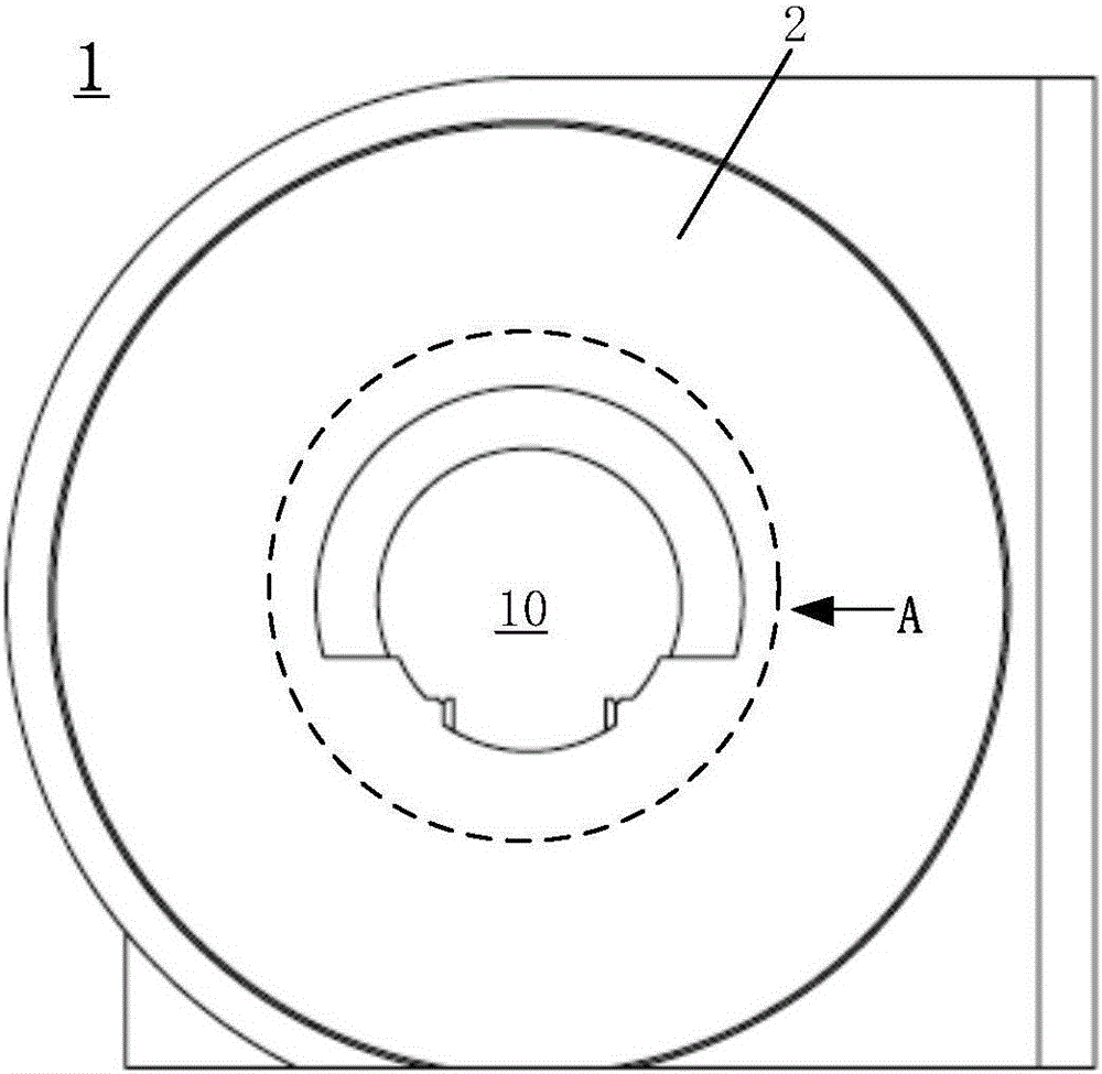
[0056] For ease of description, the embodiment of the present invention takes MR equipment as an example for illustration, but is not limited thereto, and the technical solution mentioned in the present invention can be adopted in other medical equipment that performs imaging or treatment in a relat...


PUM


Abstract

The invention provides a ventilation system of medical imaging equipment. The medical imaging equipment comprises a frame, and an imaging channel formed in the frame and used for accommodating hospital beds and paints; the ventilation system comprises a fan, air outlets arranged in the imaging channel and used for performing ventilation on the imaging channel, air guide tubes connected with the fan and the air outlets, and wind direction regulating components arranged in the air outlets and used for regulating the wind directions of the air outlets. According to the ventilation system, the directions of outlet air and the force of the outlet air can be conveniently regulated according to different requirements of patients, and the comfort of the patients is effectively improved.

Description

technical field [0001] The invention relates to medical imaging equipment, in particular to a ventilation system and a ventilation control method for the imaging channel of the medical imaging equipment to ventilate. Background technique [0002] Existing medical imaging equipment, such as computer tomography equipment (hereinafter referred to as CT equipment), nuclear magnetic resonance imaging equipment (hereinafter referred to as MR equipment), and positron emission computed tomography equipment (hereinafter referred to as PET-CT equipment) are all It includes a frame for imaging and an imaging channel arranged inside the frame. During imaging, a patient is carried by a movable bed outside the frame and moved into the imaging channel for imaging. [0003] However, the imaging channels of these imaging devices are relatively narrow, and the diameter of the general channel is only about 600mm. Moreover, when the MR equipment is imaging, the magnetic field will have a SAR ef...

Claims


Application Information

Patent Timeline
Patent Type & Authority Applications(China)
IPC IPC(8): F24F7/007F24F13/06F24F13/10
CPCF24F7/007F24F13/06F24F13/10
Inventor 李超宁罗小鹏王明超
Owner SHANGHAI UNITED IMAGING HEALTHCARE
Why Eureka
Try Eureka