A casing condenser

A condenser and sleeve type technology, which is applied to the field of sleeve type condensers for air source heat pump devices, can solve the problems of restricting water flow, extending the exchange path, and bulky condenser volume, so as to achieve increased flow and long heat exchange distance. , The effect of preventing insufficient heat release

Active Publication Date: 2018-07-06
SUZHOU HOTFROM HEAT PUMP EQUIP TECH CO LTD
View PDF8 Cites 0 Cited by
  • Summary
  • Abstract
  • Description
  • Claims
  • Application Information

AI Technical Summary

Problems solved by technology

But for a general condenser, if the path of heat exchange is too long, it will lead to a large volume of the entire condenser
At the same time, while extending the exchange path, the diameter of the tube-side channel (that is, the channel through which water flows) should be reduced as much as possible, so that the water temperature can be heated up quickly, but this will limit the flow of water

Method used


Image

  • A casing condenser
  • A casing condenser
  • A casing condenser

Examples


Embodiment Construction

[0028] The present invention will be further described below in conjunction with specific embodiments and accompanying drawings.

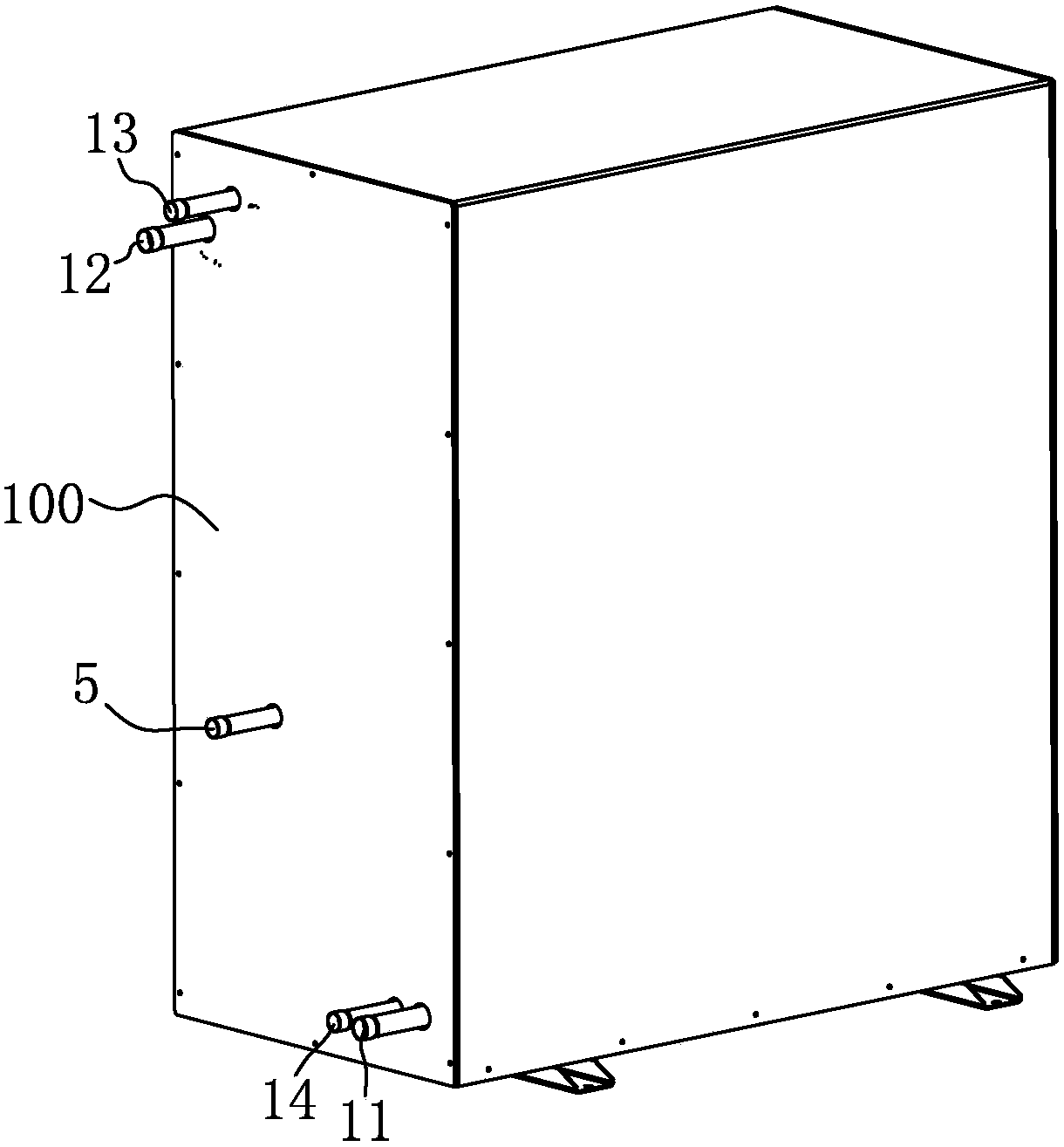
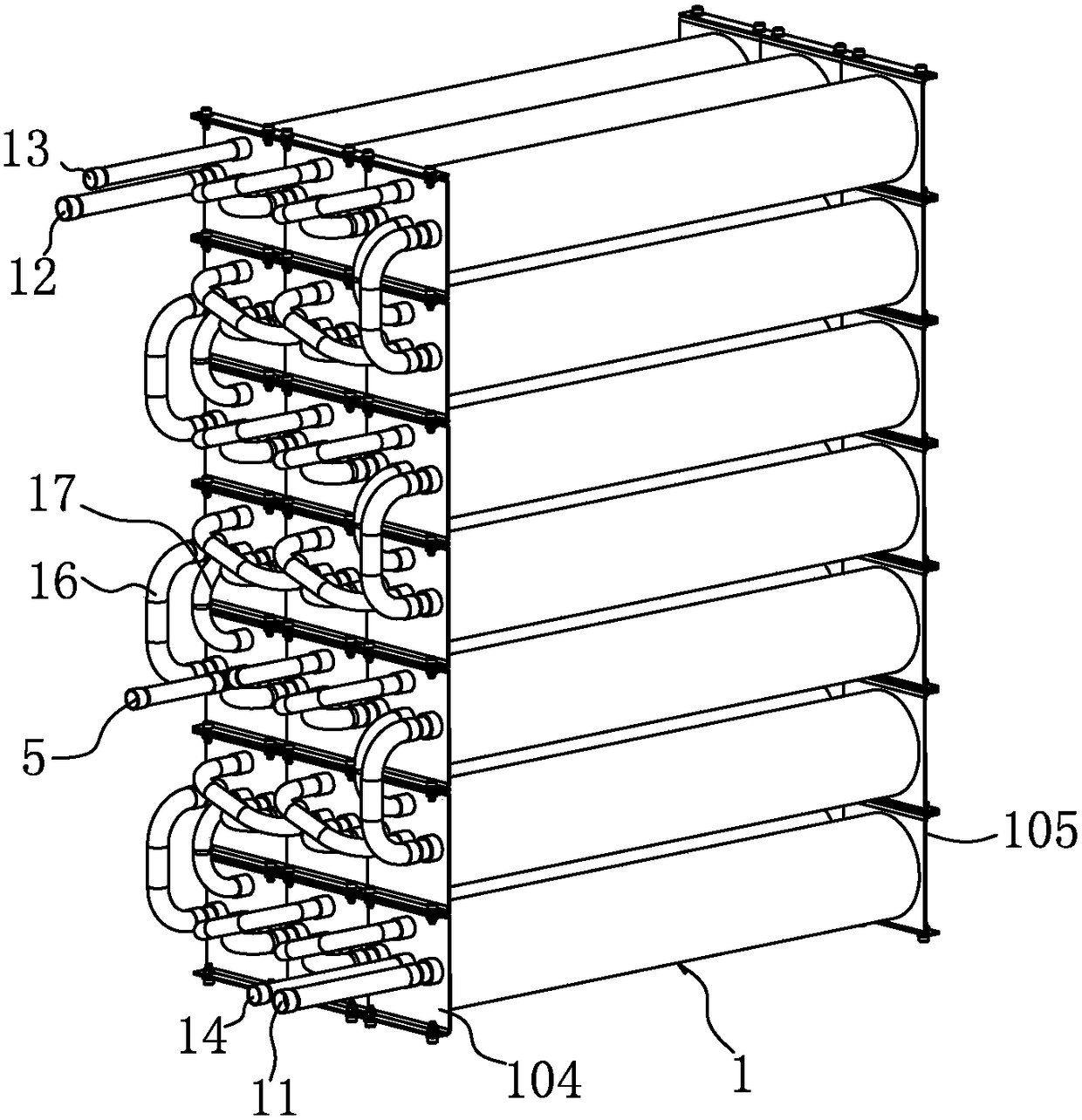
[0029] See Figure 1-6 As shown, the present invention is a casing condenser, which is composed of a plurality of condenser units 1 connected in series, and these condenser units 1 are neatly installed in the cabinet body 100 in an array.

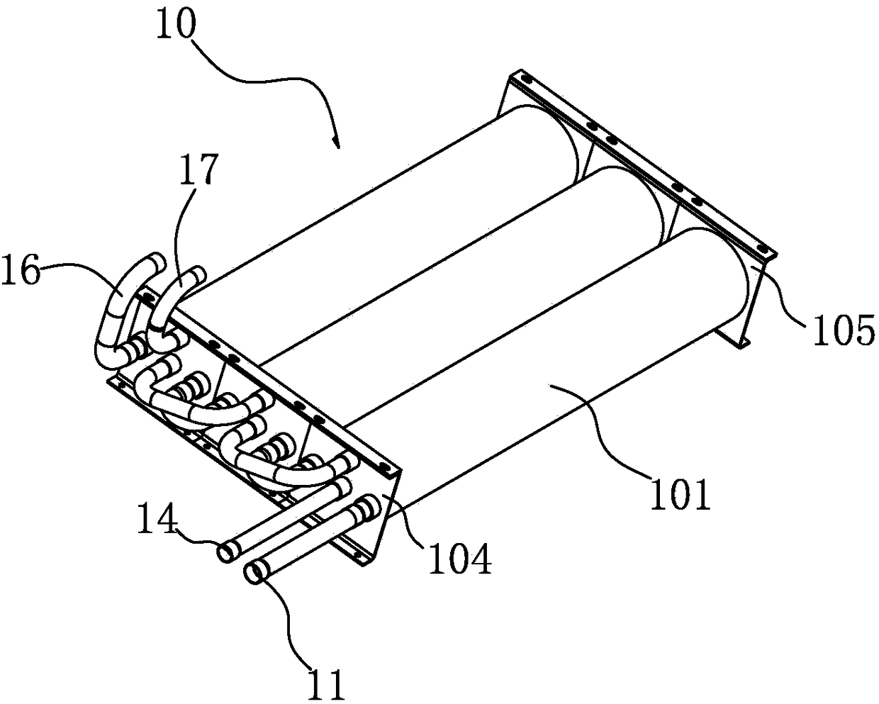
[0030] see Figure 2-5 As shown, the condenser unit 1 has a water inlet 11, a water outlet 12, a refrigerant inlet 13 and a refrigerant outlet 14, and a mutually isolated tube-side channel and a shell-side channel are formed in each condenser unit 1. The tube-side channel communicates with the water inlet 11 and the water outlet 12; the shell-side channel communicates with the refrigerant inlet 13 and the refrigerant outlet 14.

[0031] The condenser unit 1 includes: a tubular shell 101, in which at least two parallel and coiled water pipes are arranged. A front cover 104 and a rear cover 105 are fixed on the...


PUM


Abstract

The invention discloses a tube-in-tube condenser for an air source heat pump device. The tube-in-tube condenser comprises a plurality of condenser units. The condenser units are serially connected with one another, water inlets, water outlets, refrigerant inlets and refrigerant outlets are formed in the condenser units, tube pass channels and shell pass channels which are separated from one another are formed in each condenser unit, and each tube pass channel comprises at least two parallel and twined water pipes; the shell pass channels are communicated with the refrigerant inlets and the refrigerant outlets. The tube-in-tube condenser has the advantages that the tube-in-tube condenser comprises the multiple condenser units, the condenser units are distributed by means of arraying, accordingly, the sufficient condenser units can be mounted in limited spaces, heat exchange paths with sufficient lengths can be obtained, and the heat exchange efficiency can be improved; the condenser units are of parallel tube-in-tube structures, so that the lengths of the tube pass channels can be extended to the greatest extent in limited spaces of tubular shells, and the long heat exchange distances can be obtained; the flow of water can be improved.

Description

Technical field: [0001] The invention relates to the technical field of heat pump products, in particular to a casing condenser for an air source heat pump device. Background technique: [0002] The working principle of the heat pump system is the same as that of the refrigeration system. The refrigeration system (compression refrigeration) generally consists of four parts: compressor, condenser, throttle valve, and evaporator. Its working process is: low-temperature and low-pressure liquid refrigerant (such as Freon), first absorbs heat from a high-temperature heat source (such as normal temperature air) in an evaporator (such as an air-conditioning indoor unit) and vaporizes into low-pressure steam. Then the refrigerant gas is compressed into high-temperature and high-pressure vapor in the compressor, and the high-temperature and high-pressure gas is cooled and condensed into high-pressure liquid by a low-temperature heat source (such as cooling water) in the condenser. ...

Claims


Application Information

Patent Timeline
Patent Type & Authority Patents(China)
IPC IPC(8): F25B39/04
CPCF25B39/04F25B2339/047
Inventor 郑剑泽李昌
Owner SUZHOU HOTFROM HEAT PUMP EQUIP TECH CO LTD
Why Eureka
Try Eureka