U-shaped heat pipe array device and air conditioning system with the same

A technology of heat pipes and arrays, which is applied in the field of heat exchange, can solve the problems of adverse effects of heat pipes and thermosiphons on heat exchange performance, inconvenience of large-scale manufacturing and filling, and inability to make complex loops, etc., to achieve uneven distribution of cold and heat sources. , industrial design and manufacture are convenient, and the accuracy of filling rate is easy to guarantee.

Inactive Publication Date: 2016-07-13
INST OF ENGINEERING THERMOPHYSICS - CHINESE ACAD OF SCI +1
View PDF6 Cites 4 Cited by
  • Summary
  • Abstract
  • Description
  • Claims
  • Application Information

AI Technical Summary

Problems solved by technology

[0007] 1. In the process of regulating the indoor environment, in order to meet the requirements of dehumidification, the temperature of the chilled water needs to be lowered to below 7°C, and the temperature control of the room does not require such a low-temperature cold source, resulting in a waste of energy quality
[0008] 2. Although the humidity of the air after condensation and dehumidification meets the requirements, the comfort of the room is reduced due to the low temperature. In order to improve the comfort, sometimes it needs to be reheated, resulting in further waste and loss of energy
[0009] 3. Ordinary heat pipe arrays are made by combining independent heat pipes and thermosiphons. These heat pipes and thermosiphons are all single structures and cannot be made into complex circuits. This not only brings inconvenience to large-scale manufacturing and filling, but also There will be problems with uneven temperature and humidity distribution
In addition, U-shaped arrangement is required for heat recovery of air conditioners, which will adversely affect the heat transfer performance of heat pipes and thermosiphons
The vapor and liquid in the ordinary heat pipe work in the form of countercurrent, and the U-shaped structure makes it difficult to return the liquid
The thermosiphon works in the form of vapor-liquid two-phase circulation convection, and the U-shaped structure will increase the flow resistance and cause unstable work

Method used


Image

  • U-shaped heat pipe array device and air conditioning system with the same
  • U-shaped heat pipe array device and air conditioning system with the same
  • U-shaped heat pipe array device and air conditioning system with the same

Examples


Embodiment Construction

[0041] In order to make the object, technical solution and advantages of the present invention clearer, the present invention will be further described in detail below in conjunction with specific embodiments and with reference to the accompanying drawings. In the specification, the same or similar reference numerals designate the same or similar components. The following description of the embodiments of the present invention with reference to the accompanying drawings is intended to explain the general inventive concept of the present invention, but should not be construed as a limitation of the present invention.

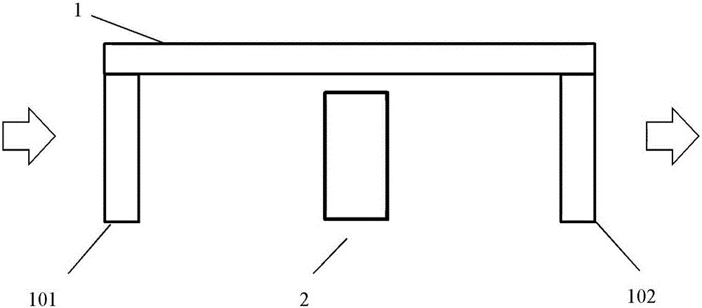
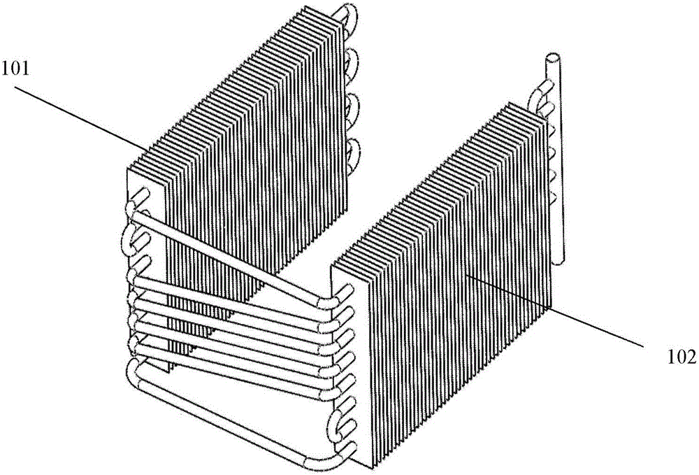
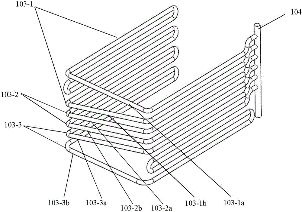
[0042] According to the general inventive concept of the present invention, a U-shaped heat pipe array device is provided, comprising two straight arm parts and a curved part connecting the two straight arm parts, wherein:

[0043] One of the two straight arm parts is a condensation end, and the other is an evaporation end, both of which include multiple horizont...


PUM


Abstract

The invention discloses a U-shaped heat pipe array device. The U-shaped heat pipe array device comprises two straight arm parts and a bend part for connecting the two straight arm parts. The two straight arm parts serve a condensation end and an evaporation end and each comprise multiple horizontal pipes; the bend part is a multi-way pipe and used for connecting the horizontal pipes of the condensation end and the horizontal pipes of the evaporation end; a perpendicular primary pipe is further arranged at the end, far away from the bend part, of the condensation end, and is communicated with the multiple horizontal pipes of the condensation end; every two corresponding end openings in the portions, far away from the bend part, of the horizontal pipes of the evaporation end are connected through a connecting pipe. According to the U-shaped heat pipe array device, in air conditioning of the air conditioner industry, the refrigeration industry, the dehumidification industry, the drying industry and the like, as low-temperature cold sources do not need to be prepared for dehumidifying during room temperature control, the use ratio of energy and the comfort degree of the room are increased.

Description

technical field [0001] The present invention relates to the field of heat exchange, and further relates to a U-shaped heat pipe array device and an air conditioning system including the device. Background technique [0002] According to the energy-saving design standard for public buildings (GB50189-2005), the indoor temperature in summer is 25°C, and the relative humidity is 40%-60%. According to this requirement, the dew point temperature of the air is 16.6°C. Therefore, the task of the air conditioner can be regarded as extracting heat from the 25°C environment and discharging it to the outdoor environment, and dehumidifying the indoor air at a dew point temperature of 16.6°C. [0003] At present, the temperature control and dehumidification of air conditioners use low-temperature refrigerated water to cool and condense the air for dehumidification, and then send the cooled and dry air into the room to achieve the purpose of heat and humidity removal. [0004] In this pr...

Claims


Application Information

Patent Timeline
Patent Type & Authority Applications(China)
IPC IPC(8): F28D15/02F24F13/30
CPCF24F13/30F28D15/0233
Inventor 姜玉雁郭朝红赵建忠郭聪王涛
Owner INST OF ENGINEERING THERMOPHYSICS - CHINESE ACAD OF SCI
Why Eureka
Try Eureka