Liquid crystal display panel

A liquid crystal display panel and substrate technology, applied in nonlinear optics, instruments, optics, etc., can solve problems such as incomplete development, poor ITO contact holes, and affect the quality of liquid crystal panels, so as to increase the number of masks, increase step differences, and improve redundancy. The rest of the effect

Inactive Publication Date: 2016-07-13
TCL CHINA STAR OPTOELECTRONICS TECH CO LTD
View PDF8 Cites 14 Cited by
  • Summary
  • Abstract
  • Description
  • Claims
  • Application Information

AI Technical Summary

Problems solved by technology

However, PFA needs to open holes. In order to minimize the height difference, the thickness of PFA should reach 4-6μm or even thicker. In this case, the opening of the holes is easy to cause incomplete development and lead to poor ITO contact holes, which will affect the quality of the LCD panel.

Method used


Image

  • Liquid crystal display panel
  • Liquid crystal display panel
  • Liquid crystal display panel

Examples


Embodiment Construction

[0025] The specific implementation manners of the liquid crystal display panel provided by the present invention will be described in detail below in conjunction with the accompanying drawings.

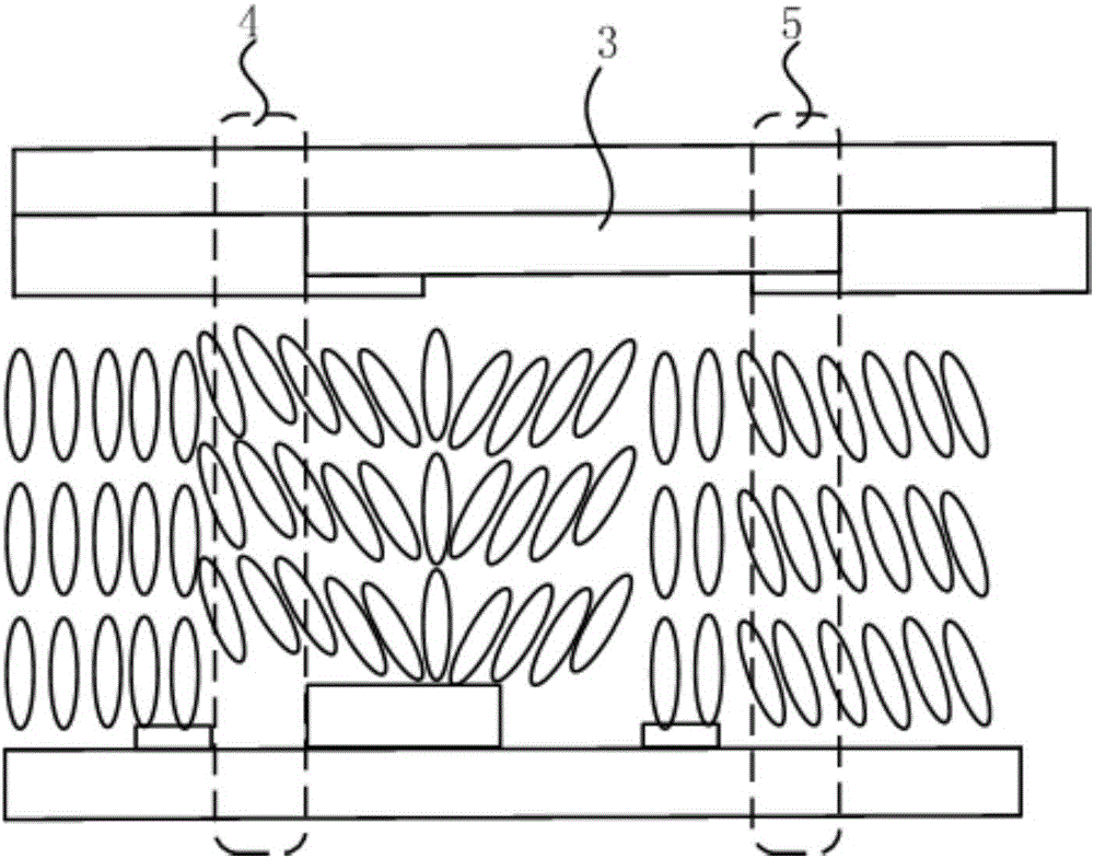
[0026] The invention provides a liquid crystal display panel, see Figure 4 The first embodiment of the liquid crystal display panel of the present invention includes an array substrate 100 and a color filter substrate 200 , and liquid crystals (not shown in the drawings) are filled between the array substrate 100 and the color filter substrate 200 .

[0027] The array substrate 100 includes a substrate substrate 101, a thin film transistor 102 disposed on the substrate substrate 101, a first passivation layer 103 disposed on the thin film transistor 102, a first passivation layer 103 disposed on the first passivation The color resistance layer 104 on the layer 103 , the second passivation layer 105 disposed on the color resistance layer 104 , and the pixel electrode layer 106 dispose...


PUM


Abstract

The invention provides a liquid crystal display panel used for display. The liquid crystal display panel comprises an array substrate and a color film substrate. The portion between the array substrate and the color film substrate is filled with liquid crystals. The array substrate comprises a color resistor layer. The color resistor layer comprises multiple color resistors arranged in a matrix mode. A stacking region formed by stacking of two color resistors with different colors is arranged between every two adjacent color resistors. The color film substrate comprises a main gap light resistor arranged corresponding to the stacking regions. The color film substrate further comprises a protective layer. The protective layer is arranged on the surface, facing the array substrate, of the color film substrate and covers the surface, not provided with the main gap light resistor, of the color film substrate. The liquid crystal display panel has the advantages that peripheral light shielding performance is improved, the segment difference between a main BPS and an auxiliary BPS is increased, redundancy of LC margin is improved, the risk of incomplete development of a polymer film is avoided, the number of photomasks is not increased, and loss of the color gamut quality is not needed.

Description

technical field [0001] The invention relates to the field of liquid crystal display, in particular to a liquid crystal display panel. Background technique [0002] In order to increase the aperture ratio of the LCD panel and reduce the production cost, the current array substrate adopts COA (color filter on array) technology, that is, the RGB color resistance on the color filter substrate (CF) side is moved to the array substrate, and only the black matrix layer is reserved on the color filter substrate side. (BM), ITO electrode (VAtype) and PS. A further step is to remove the BM film layer and replace the traditional BM with RB color resist stacking. see figure 1 As shown, the transmission spectrum of red light (R) and blue light (B) is quite different, resulting in a significant decrease in the light that passes through the overlapping of two layers of color resists, thereby achieving the effect of BM. At the same time, the original transparent photoresist gap (PS) is r...

Claims


Application Information

Patent Timeline
Patent Type & Authority Applications(China)
IPC IPC(8): G02F1/1362G02F1/1335
CPCG02F1/133512G02F1/1362G02F1/136227G02F1/133519G02F1/136222
Inventor 叶成亮林永伦
Owner TCL CHINA STAR OPTOELECTRONICS TECH CO LTD
Why Eureka
Try Eureka