High voltage adjustable transformer with over-travel protection

A transformer and over-travel technology, applied in variable transformers, transformers, variable inductors, etc., can solve the problem that the output voltage cannot be accurately controlled, and achieve the effect of avoiding over-travel rotation and improving the output voltage accuracy.

Active Publication Date: 2017-12-26
YANCHENG POWER SUPPLY CO STATE GRID JIANGSU ELECTRIC POWER CO +4
View PDF3 Cites 0 Cited by
  • Summary
  • Abstract
  • Description
  • Claims
  • Application Information

AI Technical Summary

Problems solved by technology

[0005] Another purpose of the present invention is to provide a high-voltage adjustable transformer with over-travel protection in view of the design defects of the above adjustable transformer. A first reduction box and a second reduction box are arranged on the transformer. connection, the output shaft of the second reduction box is connected to the rotor shaft, an electromagnetic clutch is provided on the second reduction box, and the second reduction box is controlled by the electromagnetic clutch to selectively link the motor and the rotor shaft, and the transformer is set in the controller Preset the voltage, then the controller controls the electromagnetic clutch to link the motor and the rotor shaft, and the motor drives the rotor shaft to rotate to adjust the transformation ratio of the transformer. At the same time, the voltage collector collects the output voltage of the transformer in real time. When the output voltage of the transformer reaches the preset voltage, The controller controls the separation of the electromagnetic clutch motor and the rotor shaft, and the rotor shaft stops rotating quickly, avoiding the over-travel rotation of the rotor shaft, and realizing the precise adjustment of the output voltage of the transformer. The invention solves the problem that the output voltage cannot be accurately controlled due to the over-rotation of the rotor shaft technical problem

Method used


Image

  • High voltage adjustable transformer with over-travel protection
  • High voltage adjustable transformer with over-travel protection
  • High voltage adjustable transformer with over-travel protection

Examples


Embodiment Construction

[0030] The present invention will be further described in detail below in conjunction with the accompanying drawings, so that those skilled in the art can implement it with reference to the description.

[0031] It should be understood that terms such as "having", "comprising" and "including" as used herein do not entail the presence or addition of one or more other elements or combinations thereof.

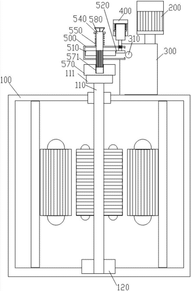
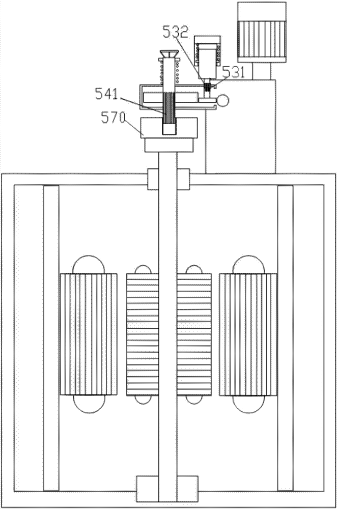
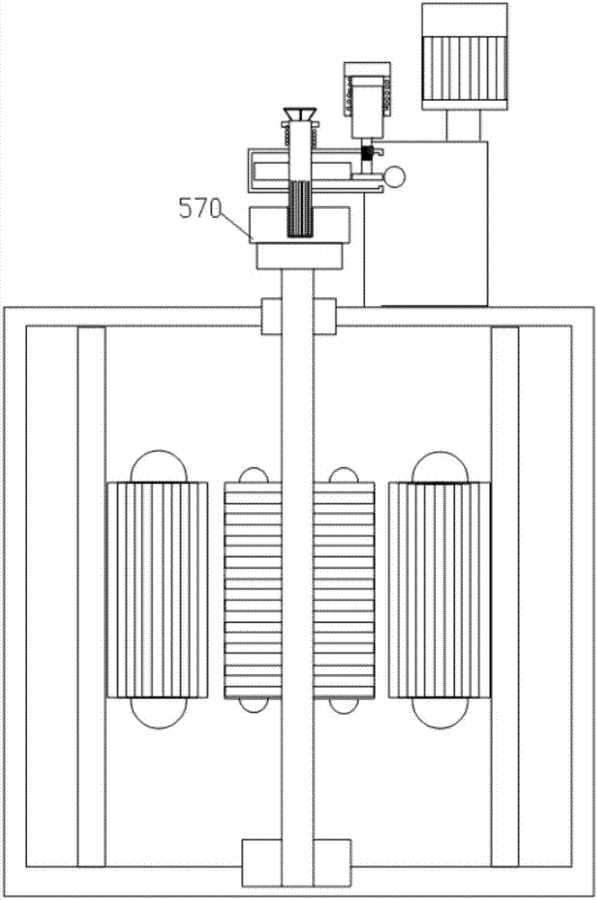
[0032] Such as Figure 1-5 As shown, the present invention provides a high-voltage adjustable transformer with over-travel protection, including:

[0033] The rotor shaft 110 is drawn from the upper end of the transformer body 100. The upper end of the rotor shaft 110 is provided with a rotor gear 111. By rotating the rotor gear 111, the rotor shaft is rotated, thereby changing the relative electrical angle of the stator and the rotor, thereby To adjust the output voltage value of the transformer;

[0034] The first reduction box 300 is arranged on the upper end of the body 100...


PUM


Abstract

The invention discloses a high-voltage adjustable transformer with an over-travel protection function.The high-voltage adjustable transformer comprises a rotor shaft, a first reduction gearbox, a second reduction gearbox and a voltage collector.The rotor shaft is led out of the upper end of a body of the transformer, and a rotor gear is arranged at the upper end of the rotor shaft.A motor is arranged on the first reduction gearbox, and an output shaft of the motor is connected with an input shaft of the first reduction gearbox.The second reduction gearbox is erected at the upper end of the rotor gear, an electromagnetic clutch is arranged on the second reduction gearbox and connected with the input end of the second reduction gearbox, an input end gear of the second reduction gearbox is selectively connected with an output shaft of the first reduction gearbox, and the output end of the second reduction gearbox is provided with a linkage plate connected with the rotor gear in an engaged mode.The voltage collector is arranged at the output end of the transformer.The technical problem that output voltages cannot be precisely controlled due to over-rotation of the rotor shaft is solved through the transformer.

Description

technical field [0001] The invention relates to a high-voltage adjustable transformer, more specifically, the invention relates to a high-voltage adjustable transformer with over-travel protection. Background technique [0002] In the field of high-voltage power transmission and distribution technology, adjustable transformers play a pivotal role. Specifically, transformers are devices that use the principle of electromagnetic induction to change AC voltage. The main components include primary coils, secondary coils, iron cores or magnetic cores. The main functions are: voltage conversion, current conversion, impedance conversion, isolation, voltage stabilization, etc. According to the application, it can be divided into: distribution transformer, power transformer, fully sealed transformer, combined transformer, rectifier transformer, etc. Although there are many types of existing transformers, most of them are designed as a specific transformer structure. For some special ...

Claims


Application Information

Patent Timeline
Patent Type & Authority Patents(China)
IPC IPC(8): H01F29/00H01F27/00H02P13/00H02K7/10H02K7/116
CPCH01F27/00H01F29/00H02K7/10H02K7/116H02P13/00
Inventor 岳志刚于峰刘建华顾宙声张怡
Owner YANCHENG POWER SUPPLY CO STATE GRID JIANGSU ELECTRIC POWER CO
Why Eureka
Try Eureka