DC load isolation switch

A technology of isolating switch and DC load, applied in the field of DC switch appliances, can solve the problem of inability to meet the breaking capacity requirements of DC traction power supply system, and achieve the effect of light weight, convenient installation and maintenance, and compact structure

Inactive Publication Date: 2016-07-13
中国船舶重工集团公司第七一二研究所 +1
View PDF2 Cites 14 Cited by
  • Summary
  • Abstract
  • Description
  • Claims
  • Application Information

AI Technical Summary

Problems solved by technology

[0004] However, the existing load disconnectors in the domestic and foreign markets are only suitable for AC p...

Method used


Image

  • DC load isolation switch
  • DC load isolation switch
  • DC load isolation switch

Examples


Embodiment Construction

[0025] The present invention will be described in further detail below in conjunction with the accompanying drawings.

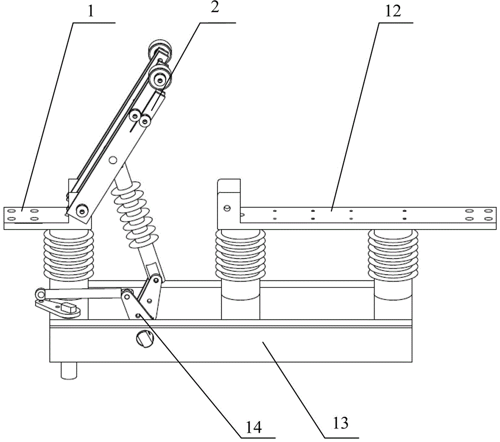
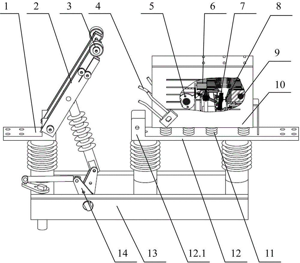
[0026] refer to Figure 1 to Figure 4 As shown, the present invention discloses a DC load disconnector, which is composed of a disconnector installed on an insulating support base 13 as a main switch and a load switch as an arc switch. The disconnector includes a connecting insulating support The moving contact busbar 1 of the base 13 and the crankshaft connecting rod mechanism 14, the crankshaft connecting rod mechanism 14 is connected with an insulating operating rod, the moving contact busbar 1 is movably connected with an isolating knife 2, and the isolating knife 2 consists of two sets of copper bars Formed side by side, the static contact 12.1 can be clamped in the middle and separated and closed in a sliding manner. The isolation knife 2 and the static contact busbar 12 are made of red copper, which improves the electrical conductivity and reduces the ...


PUM


Abstract

The invention discloses a DC load isolation switch, which comprises an isolation switch and a load switch, wherein the isolation switch comprises a moving contact busbar and a crankshaft mechanism; an insulated operation rod is connected onto the crankshaft mechanism; isolation knives are arranged on the moving contact busbar; the end part of the insulated operation rod is connected with the isolation knives; conductive wheels are arranged on the isolation knives; the load switch comprises a static contact busbar, a fast operation mechanism and an arc extinguishing chamber; a static contact is arranged on the static contact busbar; and U-shaped conductive forks corresponding to the conductive wheels are arranged on the fast operation mechanism. The DC load isolation switch of the invention adopts a structure form of combining the load switch and the isolation switch, the isolation switch part uses a structure of an upper knife and a lower knife, normal load current in a line can be opened and closed, functions of the isolation switch can be integrated, and the DC load isolation switch has the advantages of compact structure, strong opening ability, convenient mounting and maintenance and the like.

Description

technical field [0001] The invention belongs to the technical field of DC switching devices, and in particular relates to a DC load isolating switch. Background technique [0002] At present, in domestic and foreign urban rail transit DC traction power supply systems, the catenary structure is divided into two power supply forms: contact rail and overhead catenary. The power supply form of the overhead catenary is to use the isolating switch on the column to form a large bilateral power supply. Since the isolating switch cannot be switched on and off with load, when the power grid is faulty, the power supply needs to be cut off, and then the isolating switch is closed to withdraw the fault point from the grid, and then Restart the power supply. This undoubtedly brings inconvenience to urban rail transit, and will cause traffic paralysis in severe cases. [0003] Therefore, there is a need for a DC load isolating switch to replace the original pole-mounted isolating switch,...

Claims


Application Information

Patent Timeline
IPC IPC(8): H01H31/04H01H33/10H01H33/18
CPCH01H31/04H01H33/10H01H33/185
Inventor 刘哲乐洪有钟积科沈文李明
Owner 中国船舶重工集团公司第七一二研究所
Why Eureka
Try Eureka