
Trigger of high speed and low power consumption

A flip-flop and low power consumption technology, applied in the direction of reducing power consumption, reducing power of field effect transistors, reducing power through control/clock signals, etc., can solve inapplicable, large on-resistance, and parasitic capacitance at the output of the flip-flop Large and other problems, to achieve the effect of no static power consumption and increased speed

Active Publication Date: 2016-07-13
CHONGQING GIGACHIP TECH CO LTD
View PDF3 Cites 5 Cited by
  • Summary
  • Abstract
  • Description
  • Claims
  • Application Information

AI Technical Summary

Problems solved by technology

However, the control signal generation circuit and the enable transistor of the latch are both composed of NMOS transistors connected in series, and the on-resistance is relatively large. At the same time, the parasitic capacitance at the output end of the flip-flop is also relatively large, which is not suitable for high-speed circuit design.

Method used


Image

  • Trigger of high speed and low power consumption
  • Trigger of high speed and low power consumption
  • Trigger of high speed and low power consumption

Examples


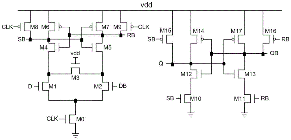
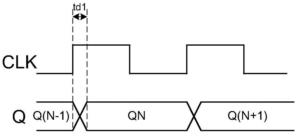
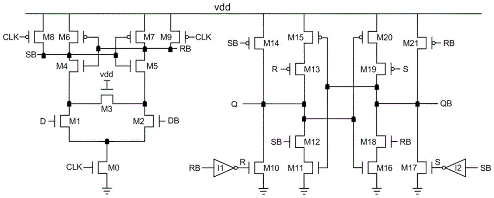
Embodiment Construction

[0027] The preferred embodiments of the present invention will be described in detail below in conjunction with the accompanying drawings; it should be understood that the preferred embodiments are only for illustrating the present invention, rather than limiting the protection scope of the present invention.

[0028] The schematic diagram of the structure of the high-speed low-power flip-flop proposed by the present invention is as follows: Figure 7 As shown, a high-speed low-power flip-flop includes a control signal generating circuit, an enabling unit, and a latch structure. The latch structure includes a first input terminal, a second input terminal, a first output terminal, and a second input terminal. Two output terminals, a first enable terminal, a second enable terminal and a ground terminal, the enable unit includes a first enable circuit and a second enable circuit, the output signal X of the control signal generating circuit and the external control The signal D is...


PUM


Abstract

The invention discloses a trigger of high speed and low power consumption. The trigger comprises a control signal generation circuit, an enablement unit and a latch register structure, n the latch register structure comprises two input ends, two output ends, two enablement ends and a grounding end; the enablement unit comprises two enablement circuits; an output signal X and an external control signal D of the control signal generation circuit serve as input signals of the first enablement circuit, and the output end of the first enablement circuit is connected with the first enablement end; and anti-phase signals DB of the output signal X and the external control signal D of the control signal generation circuit serves as input signals of the second enablement circuit, and the output end of the second enablement circuit is connected with the second enablement end. Compared with a traditional structure, the circuit structure of the trigger in the invention is simpler; and the parasitic capacitance of the output end of a latch register is very low, the speed of the trigger is improved, and there is no static power consumption.

Description

technical field [0001] The invention belongs to the technical field of analog or digital-analog hybrid integrated circuits, and relates to a high-speed and low-power consumption trigger. Background technique [0002] As an important sequential circuit structure, flip-flop is widely used in digital, analog and analog-digital hybrid integrated circuits. In recent years, with the continuous development of integrated circuit manufacturing technology, the demand for high-speed low-power flip-flops has gradually increased. In order to meet the requirements of low power consumption, the power supply voltage has been further reduced. In response to this trend, in order to ensure the working performance of flip-flops , developed some high-speed low-power flip-flop structures, including SAFF (sense amplifier based flip-flop) structure, MSAFF (modified sense amplifier based flip-flop) and SBFF (self-blocking flip-flop) structure, the above three structures have their own advantages and...

Claims


Application Information

Patent Timeline
Patent Type & Authority Applications(China)
IPC IPC(8): H03K3/012H03K3/356
CPCH03K3/012H03K3/356008H03K3/356139H03K3/356173H03K3/356182H03K3/35625H03K19/0013H03K19/0016H03K3/037
Inventor 徐代果胡刚毅李儒章王健安陈光炳王育新付东兵刘涛刘璐邓民明石寒夫王旭
Owner CHONGQING GIGACHIP TECH CO LTD
Learn More