Vapor chamber and manufacturing method thereof

A technology of vapor chamber and manufacturing method, which is applied in cooling/ventilation/heating transformation, lighting and heating equipment, indirect heat exchangers, etc., and can solve problems such as affecting heat dissipation effect and reducing the volume of cavity 12

Active Publication Date: 2018-09-07
AVARY HLDG (SHENZHEN) CO LTD +1
View PDF11 Cites 2 Cited by
  • Summary
  • Abstract
  • Description
  • Claims
  • Application Information

AI Technical Summary

Problems solved by technology

However, reducing the width of the cavity 12 will result in a reduction in the volume of the cavity 12, and the working fluid 14 that the cavity 12 can accommodate will also decrease, thereby affecting the heat dissipation effect.

Method used


Image

  • Vapor chamber and manufacturing method thereof
  • Vapor chamber and manufacturing method thereof
  • Vapor chamber and manufacturing method thereof

Examples


Embodiment Construction

[0027] see Figure 2 to Figure 9 , the embodiment of the present invention provides a method for manufacturing a vapor chamber 20, comprising the following steps:

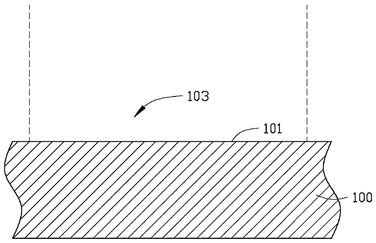
[0028] For a first step, see figure 2 , providing a first bottom plate 100 .

[0029] The material of the first bottom plate 100 is metal, such as magnesium-aluminum alloy, aluminum alloy, magnesium alloy, aluminum, copper, etc. In this embodiment, the first bottom plate 100 is a pure copper plate, and the first bottom plate 100 includes a flat The first surface 101 of the first surface 101 includes at least one cavity area 103 (only one is shown in the figure, in other embodiments, it can also be 3 or 5, when there is one more cavity area 103 , multiple cavity regions 103 are arranged side by side).

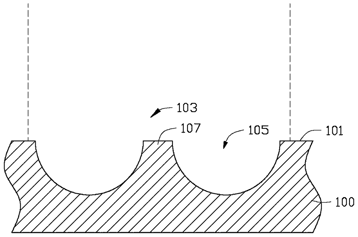
[0030] In the second step, please also refer to the image 3 and Figure 4 , etch the first surface 101 to obtain several first grooves 105 arranged side by side in each cavity area 103 (only two are shown in t...


PUM


Abstract

The invention provides a manufacturing method of a temperature-uniforming plate, which comprises the steps of providing a flat first bottom plate with a first bottom surface, wherein the first bottom surface includes at least one cavity region; etching the first bottom plate to form at least two first grooves, and forming a non-etched first post between every two first grooves within the same cavity region; forming a first capillary structure on the surfaces of the first grooves and the first post; filling a working fluid in the first grooves; covering the adhesive on a first surface outside the cavity region; providing a second bottom plate with a second bottom surface, second grooves and a second post; laminating the first bottom plate and the second bottom plate together in the vacuum state to form a closed cavity by the first grooves and the second grooves; and curing the adhesive to obtain the temperature-uniforming plate. The invention also relates to a temperature-uniforming plate manufactured according to the above method.

Description

technical field [0001] The invention relates to heat dissipation, in particular to a uniform temperature plate and a manufacturing method thereof. Background technique [0002] In recent years, as the size of electronic devices gradually develops in the direction of thinner, thinner and smaller, the issue of heat dissipation of electronic devices has gradually been paid more and more attention. Especially the current consumer electronic products, such as digital cameras, mobile phones and notebook computers, etc., have more and more complex functions, and the number of power transistor components they contain is also increasing. Space is getting smaller and smaller, coupled with restrictions on the use of fans in order to reduce the noise generated by electronic devices, the problem of thermal management has become more serious and needs to be solved urgently. [0003] Among the many cooling devices, the vapor chamber, also known as flat plate heat pipe, has been widely use...

Claims


Application Information

Patent Timeline
Patent Type & Authority Patents(China)
IPC IPC(8): H05K7/20
CPCF28D15/0233F28D15/046
Inventor 胡先钦沈芾云雷聪何永强何明展
Owner AVARY HLDG (SHENZHEN) CO LTD
Why Eureka
Try Eureka