Multidirectional stirring equipment

A stirring equipment and multi-directional technology, applied to mixers with rotating stirring devices, chemical instruments and methods, mixers, etc., can solve the problems of low probability of mutual contact, high energy consumption, dangerous electricity consumption, and uniform mixing of materials, etc. , to achieve the effect of improving production efficiency, increasing mutual contact time, and low energy consumption

Inactive Publication Date: 2016-07-20
XUZHOU BEIER ELECTRIC CO LTD
View PDF0 Cites 6 Cited by
  • Summary
  • Abstract
  • Description
  • Claims
  • Application Information

AI Technical Summary

Problems solved by technology

[0002] Stirring equipment is often used in the preparation process of some slurry products. The existing stirring method usually uses the stirring shaft to continuously rotate in a certain direction for a certain period of time. The materials in the equipment are basically driven by the stirring paddle. And the whole is mixed together, the probability of mutual contact is small and the contact time is short, especially when the raw materials of some products are relatively viscous and viscous, it is difficult to stir evenly, and it is difficult to stir the materials evenly in a short time; in addition, Most of the stirring shafts are driven by high-power motors, which consume a lot of energy and are dangerous to use electricity.

Method used


Image

  • Multidirectional stirring equipment

Examples


Embodiment Construction

[0010] The present invention will be described in further detail below in conjunction with the accompanying drawings.

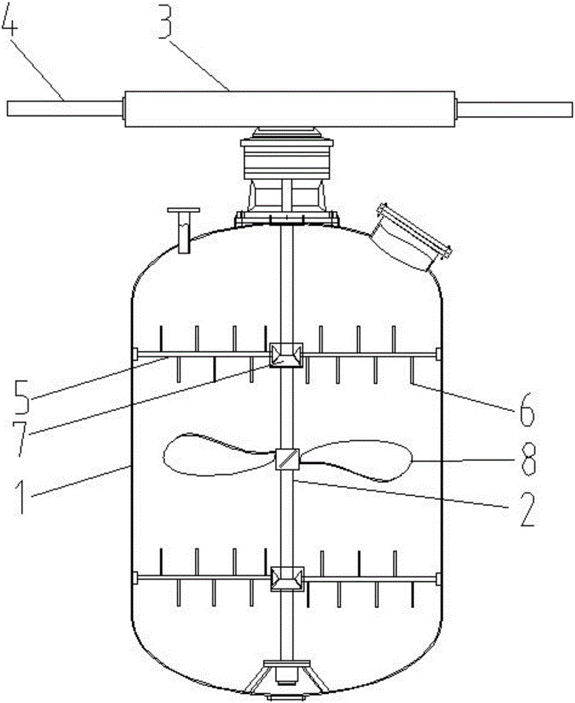
[0011] Such as figure 1 The multi-directional stirring equipment shown includes a stirring tank body 1 and a stirring shaft 2. The stirring shaft 2 penetrates vertically from the top of the stirring tank body 1 into the stirring tank body 1. The stirring shaft 2 is driven to rotate by a driving device, and the driving device includes teeth Bar box 3, one end of the stirring shaft 2 extending out from the stirring tank body 1 is connected with the rack in the rack case 3 through gears, the two ends of the rack are respectively connected with an oil cylinder 4, and the stirring shaft 2 is distributed with There are two sets of fixed stirring parts, each set of fixed stirring parts includes two stirring rods 5 symmetrically arranged on the stirring shaft 2, a plurality of stirring blades 6 are installed on the stirring rods 5, and one end of the stirring rods 5 ...


PUM


Abstract

The invention discloses multidirectional stirring equipment.A stirring shaft perpendicularly goes deeply into a stirring tank body from the top of the stirring tank body, and is driven to rotate by a driving device, the upper end, stretching out of one end of the stirring tank body, of the stirring shaft is connected with a rack in a rack box through a gear, two oil cylinders are connected with the two ends of the rack respectively, two sets of fixing and stirring components are distributed on the stirring shaft, each fixing and stirring component comprises two stirring rods symmetrically arranged on the stirring shaft, a plurality of stirring blades are installed on each stirring rod, one end of each stirring rod is fixed to the stirring shaft through a bevel gear set, and the other end of each stirring rod is installed on a bearing pedestal on the inner wall of the stirring tank body.The multidirectional stirring equipment is simple in structure, materials can be stirred in multiple directions through the rotating stirring rods with the combination of a stirring impeller, the contact time of different materials is further prolonged by means of the back and forth reciprocating stirring mode, the stirring speed is increased, the stirring effect is improved, and the production efficiency is improved; the stirring shaft rotates under driving of the oil cylinders and the rack box, so that the energy consumption is low, and the multidirectional stirring equipment is safe to use.

Description

technical field [0001] The invention relates to a stirring device, in particular to a multi-directional stirring device. Background technique [0002] Stirring equipment is often used in the preparation process of some slurry products. The existing stirring method usually uses the stirring shaft to continuously rotate in a certain direction for a certain period of time. The materials in the equipment are basically driven by the stirring paddle. And the whole is mixed together, the probability of mutual contact is small and the contact time is short, especially when the raw materials of some products are relatively viscous and viscous, it is difficult to stir evenly, and it is difficult to stir the materials evenly in a short time; in addition, Most of the stirring shafts are driven by high-power motors, which consume a lot of energy and are dangerous to use electricity. Contents of the invention [0003] In view of the above-mentioned problems in the prior art, the object...

Claims


Application Information

Patent Timeline
Patent Type & Authority Applications(China)
IPC IPC(8): B01F7/16B01J19/18
CPCB01J19/0066B01J19/18B01F27/11B01F27/192B01F27/88B01F27/80
Inventor 周淑淑
Owner XUZHOU BEIER ELECTRIC CO LTD
Why Eureka
Try Eureka