Pipeline intersecting line projecting device and projecting method

A projection device and intersecting line technology, which is applied in measuring devices, active optical measuring devices, surveying and navigation, etc., can solve the problems of low stakeout accuracy of intersecting lines, strong pertinence of templates, troublesome follow-up processes, etc., and achieve reasonable design , improve the precision of stakeout, and have a wide range of applications

Active Publication Date: 2016-07-20
CHINA FIRST METALLURGICAL GROUP
View PDF8 Cites 15 Cited by
  • Summary
  • Abstract
  • Description
  • Claims
  • Application Information

AI Technical Summary

Problems solved by technology

At present, there are mainly two methods for setting out intersecting lines. One is manual setting out, which mainly relies on the experience of the staff to make large samples of intersecting lines. , will cause corresponding troubles to the follow-up process; the other is to use templates to draw intersecting lines. Although the precision of this method is relatively high, however, different templates must be prepared for pipes with different diameters. Therefore, there are Labor preparation time is long, the defect of high production cost, and the template is highly targeted, which is not conducive to reuse

Method used


Image

  • Pipeline intersecting line projecting device and projecting method
  • Pipeline intersecting line projecting device and projecting method
  • Pipeline intersecting line projecting device and projecting method

Examples


Embodiment Construction

[0032] In order to better understand the present invention, the present invention will be further described below in conjunction with the accompanying drawings and specific embodiments.

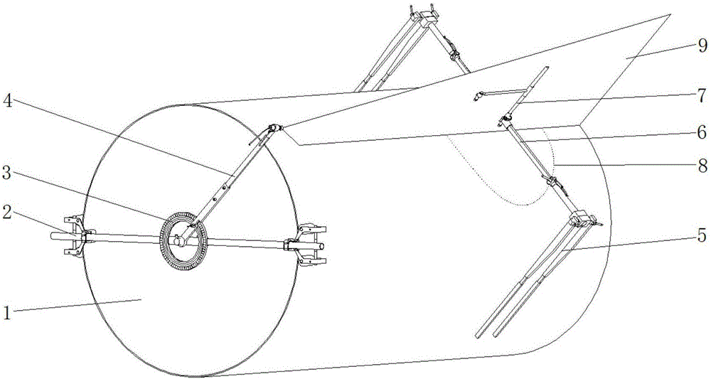
[0033] In pipeline installation engineering, multiple pipelines intersect to form intersecting lines. During installation, after the main pipe 1 is positioned, the large sample of the intersecting line 8 is released accurately earlier, and then the intersecting branch pipes are welded with the main pipe 1. Such as figure 1 As shown, the present invention provides a pipeline intersecting line pay-off system, the system includes a pipeline axis pay-off device and a pipeline intersecting line projection device, the pipeline axis pay-off device is installed on the end face of the main pipe 1, according to the branch pipeline At the intersection position with the main pipeline 1, the axis of the branch pipeline is set out on the outer wall of the main pipeline 1; the pipeline intersecting line pr...


PUM


Abstract

The invention discloses a pipeline intersecting line projecting device. The pipeline intersecting line projecting device comprises a pipeline clamping mechanism, an elevation regulation mechanism and a laser projecting mechanism. The pipeline clamping mechanism comprises a first clamping body and a second clamping body which are arranged in parallel. The elevation regulation mechanism comprises a main shaft, a regulation sleeve and a scale. One end of the main shaft is connected with the first clamping body, and the other end of the main shaft is connected with the second clamping body. The regulation sleeve is installed on the main shaft and can slide in the length direction of the main shaft. The laser projecting mechanism comprises a center shaft, a rotating shaft and a laser projector. The lower end of the center shaft is connected with the regulation sleeve. The upper portion of the center shaft is connected with one end of the rotating shaft in a rotating manner. The rotating shaft can rotate around the center shaft. The laser projector is installed at the other end of the rotating shaft. The invention further provides a pipeline intersecting line projecting method. The pipeline intersecting line projecting device and method have the main beneficial effects that a plurality of reference points are projected on the pipe wall of a pipeline through the laser projecting mechanism, an operator sequentially connects the reference points so that the intersecting line lofting work can be completed, the work efficiency is improved, and the lofting precision is improved.

Description

technical field [0001] The invention belongs to the technical field of pipeline construction, and in particular relates to a pipeline intersecting line projection device and a projection method. Background technique [0002] When multiple pipes are connected, the envelope formed by the junction between the pipes is called the intersecting line. After the main pipe is positioned, the large sample of the intersecting line must be accurately released first, and then the other pipes are welded to the main pipe. At present, there are mainly two methods for setting out intersecting lines. One is manual setting out, which mainly relies on the experience of the staff to make large samples of intersecting lines. , will cause corresponding troubles to the follow-up process; the other is to use templates to draw intersecting lines. Although the precision of this method is relatively high, however, different templates must be prepared for pipes with different diameters. Therefore, ther...

Claims


Application Information

Patent Timeline
Patent Type & Authority Applications(China)
IPC IPC(8): B25H7/00G01C15/00
CPCB25H7/005G01C15/002
Inventor 杨德志夏春
Owner CHINA FIRST METALLURGICAL GROUP
Why Eureka
Try Eureka