Large rotary disk type stone machining equipment

A stone processing and large turntable technology, applied in stone processing equipment, stone processing tools, work accessories, etc., can solve the problems of single processing procedure, large occupation area, low work efficiency, etc., to reduce the overall volume and occupy a small area. , the effect of improving work efficiency

Active Publication Date: 2016-07-20
QUANZHOU JIANENG MACHINERY MFG
View PDF7 Cites 0 Cited by
  • Summary
  • Abstract
  • Description
  • Claims
  • Application Information

AI Technical Summary

Problems solved by technology

[0003] However, in this kind of stone profiling machine, each processed workpiece is arranged side by side on the same plane in a straight line during processing, and each processed workpiece rotates synchronously. Adopting this processing method has the following defects: 1. Cause stone profiling The overall volume of the machine is large and occupies a large area; 2. When processing, it is necessary to wait for all the processed workpieces to be processed and then stop the machine before placing the next processed workpiece on the top for processing. It is impossible to remove the processed workpiece at the same time. The overall work efficiency is low; 3. Each workpiece can only be processed once (such as engraving, polishing, and cutting) each time the machine is turned on, and the processing procedure is single.

Method used


Image

  • Large rotary disk type stone machining equipment
  • Large rotary disk type stone machining equipment
  • Large rotary disk type stone machining equipment

Examples


Embodiment Construction

[0033] In order to further explain the technical solution of the present invention, it will be described in detail below in conjunction with the accompanying drawings.

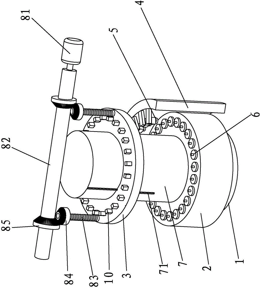
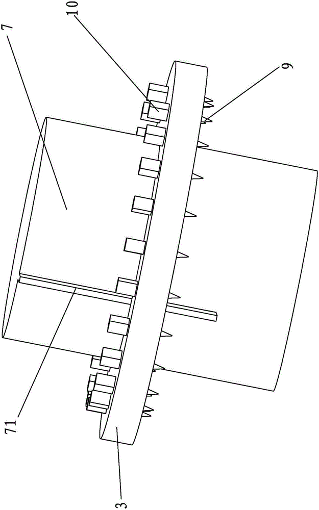
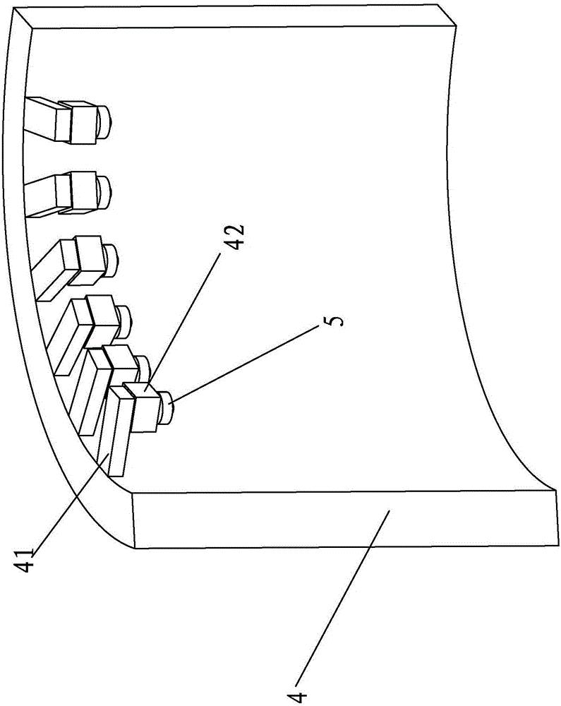
[0034] A large rotary disc stone processing equipment of the present invention, such as Figure 1-4 As shown, it includes a chassis base 1, a lower tray 2 for the workpiece to be processed to be rotated and placed on it, an upper top tray 3 that is directly above the lower tray 2 and can move up and down, and a mounting bracket 4 outside the lower tray 2; Wherein, the lower tray 2 is rotatably installed on the chassis seat 1, and the lower tray 2 is synchronously rotated and connected with the upper top tray 3. One side of the mounting bracket 4 faces the lower tray 2, and the side of the mounting bracket 4 facing the lower tray 2 is the inner side. One side of the lower pallet 2 is the outer side, and the inner side of the mounting bracket 4 is provided with several processing heads 5 for processing the workp...


PUM

PropertyMeasurementUnit
Heightaaaaaaaaaa

Abstract

The invention relates to large rotary disk type stone machining equipment. The large rotary disk type stone machining equipment comprises a bottom disk seat, a lower tray, an upper top disk and an installation frame which corresponds to the lower tray. A machined workpiece is rotationally placed on the lower tray. The upper top disk is located above the lower tray. The lower tray is rotationally installed on the bottom disk seat. The lower tray and the upper top disk are connected in a synchronous rotation mode and can get close to each other and go far away from each other relatively. The installation frame is provided with a face facing the lower tray. The face, facing the lower tray, of the installation foramen serves as an inner side face. The face, back on to the lower tray, serves as an outer side face. The inner side face of the installation frame is provided with a plurality of machining heads conducting machining treatment on the machined workpiece on the lower tray. All the machining heads are distributed at intervals in the circumferential direction of the lower tray. The large rotary disk type stone machining equipment has the advantages that the occupied area is small, the whole work efficiency is high, and machining procedures are diversified and flexible; the large rotary disk type stone machining equipment is suitable for diversified machining of modern stone, a plurality of stone machining devices do not need to be arranged, and the one-machine-multipurpose function is achieved.

Description

technical field [0001] The invention relates to processing equipment, in particular to a stone processing equipment for processing stone. Background technique [0002] Stone is widely used in leisure plazas, villas, hotels and municipal roads, etc. In order to improve the decoration and grade of stone, the surface of stone is generally processed, and the processing includes cutting, engraving or polishing. There are many equipments currently used for stone processing, such as the China State Intellectual Property Office announced on September 07, 2011, the multi-head cylindrical stone profiling machine with the authorized announcement number CN101367253B, which includes a chassis base and a column, and the column includes a corresponding The front and rear columns vertically fixed on the chassis base, the front and rear columns respectively include two columns symmetrically arranged on the chassis base, and the workpiece clamping mechanism is arranged on the front column, an...

Claims


Application Information

Patent Timeline
IPC IPC(8): B28D1/00B28D7/00B28D7/04
CPCB28D1/003B28D7/005B28D7/04
Inventor 陈锡奎
Owner QUANZHOU JIANENG MACHINERY MFG
Why Eureka
Try Eureka