Shaftless screw conveyor

A shaftless screw conveying and screw blade technology, applied in the field of screw blades, can solve problems such as irreparability, blade failure, waste of manpower and material resources, and achieve the effect of reducing maintenance costs, maintaining the same performance, and reducing waste.

Inactive Publication Date: 2016-07-20
SHANDONG HAINENG ENVIRONMENT TECH CO LTD
View PDF10 Cites 2 Cited by
  • Summary
  • Abstract
  • Description
  • Claims
  • Application Information

AI Technical Summary

Problems solved by technology

[0002] The widely used screw conveyor is composed of three parts: geared motor, blade, and cylinder, which constrain the material in the cylinder, and the reducer drives the screw blade, which is an integral blade. During normal operation, the friction between the blade and the material drives the material. Movement, to complete the transportation of materials, due to the deflection and material resistance, the spiral blade will form a bow when it is working normally, and the top of the bow will rub against the cylinder, because the top of the bow is always at the center of the blade, and this position has a fixed Therefore, the most severe friction is always this position, so this position is the first to be damaged, but because the blade is a one-piece structure, part of the damage will cause the entire blade to fail, because of its complex structure, it cannot be repaired, it can only be replaced, resulting in waste of manpower and material resources
In order to solve the deficiency that the entire blade is scrapped due to partial failure in the prior art, the present invention provides a repairable blade

Method used


Image

  • Shaftless screw conveyor
  • Shaftless screw conveyor
  • Shaftless screw conveyor

Examples


Embodiment Construction

[0017] In order to illustrate the technical solution of the present invention more clearly, the following specific embodiments will introduce the present invention in detail in conjunction with the accompanying drawings.

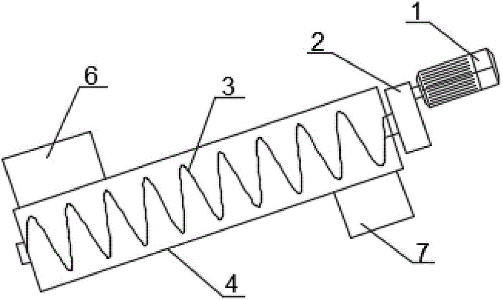
[0018] Such as Figure 1~4 As shown, a shaftless screw conveyor includes: a motor (1), a reducer (2), a screw blade (3), a cylinder (4), a liner (5), an inlet (6), an outlet (7); Wherein, cylinder body (4) one side is provided with feed inlet (6), and the other side is provided with discharge outlet (7), and motor (1) is connected with reducer (2) and is arranged on cylinder body (4) ) side, the integral structure of the screw blade (3) runs through the inside of the cylinder (4), the screw blade (3) is connected with the drive shaft of the reducer extending into the inside of the cylinder, and the liner (5) is arranged on the cylinder (4 ) inner wall.

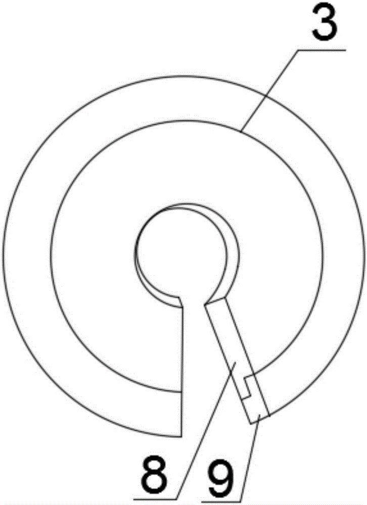
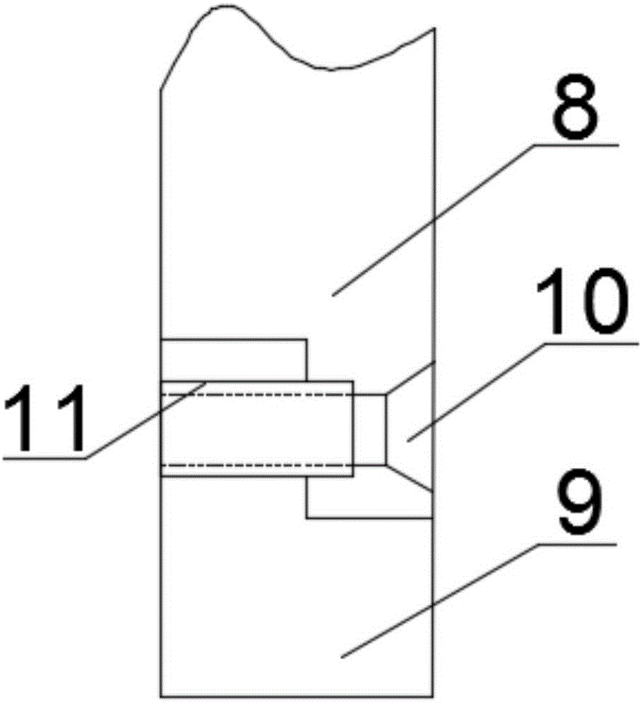
[0019] Such as figure 2 As shown, the spiral blade (3) includes: a main body part (8), a vulnerable p...


PUM


Abstract

A screw conveyor which is widely used nowadays consists of three parts of a speed reduction motor, a blade and a barrel body; a material is restricted in the barrel body; the screw blade which is driven by the speed reduction motor is an integral blade; the material is driven to move by friction between the blade and the material during normal operation so as to realize conveying of the material; friction can be generated between the screw blade and the barrel body, which can damage the screw blade gradually; but since the screw blade is of an integral structure, so that the whole blade fails when a part of the blade is damaged; and the blade needs to be changed, so that waste of manpower and material resources is caused. For solving the defect in the prior art that the whole blade is scrapped because of partial failure, a combined-type blade is adopted by the invention; the original integral blade is changed into two parts, namely a main body part and an easy-to-damage part; when the blade is abraded and fails, the blade can be conveniently repaired and changed; the later-period repair and maintenance cost is lowered; waste is reduced; and by adopting the combined-type blade, requirements on every aspect of use of the blade are met, and the use property is unchanged.

Description

technical field [0001] The invention relates to a rotary blade of a screw conveyor, in particular to a partially repairable screw blade. Background technique [0002] The widely used screw conveyor is composed of three parts: geared motor, blade, and cylinder, which constrain the material in the cylinder, and the reducer drives the screw blade, which is an integral blade. During normal operation, the friction between the blade and the material drives the material. Movement, to complete the transportation of materials, due to the deflection and material resistance, the spiral blade will form a bow when it is working normally, and the top of the bow will rub against the cylinder, because the top of the bow is always at the center of the blade, and this position has a fixed Therefore, the most severe friction is always this position, so this position is the first to be damaged, but because the blade is a one-piece structure, part of the damage will cause the entire blade to fai...

Claims


Application Information

Patent Timeline
Patent Type & Authority Applications(China)
IPC IPC(8): B65G33/26
CPCB65G33/265
Inventor 何西鲁李清彬
Owner SHANDONG HAINENG ENVIRONMENT TECH CO LTD
Why Eureka
Try Eureka