Intake mechanism of rotary engine

A technology of air intake mechanism and engine, which is applied in the direction of combustion engine, machine/engine, internal combustion piston engine, etc., and can solve the problems of insufficient fuel economy and high fuel consumption

Active Publication Date: 2018-06-12
侯春景
View PDF6 Cites 0 Cited by
  • Summary
  • Abstract
  • Description
  • Claims
  • Application Information

AI Technical Summary

Problems solved by technology

However, every time the high-pressure air in the combustion chamber of the above-mentioned rotary engine enters, the engine works once, and most engines in the prior art adopt the mode that the cam and the valve rod cooperate to realize the opening and closing of the valve rod. The timing pulley system of the engine is connected to realize the continuous air intake of the starting valve stem. Although the above-mentioned mechanical method can realize the air intake of the valve stem, when it is applied to the rotary engine, the runner does not rotate once, and the valve stem It is opened only once, therefore, the fuel consumption of the corresponding rotary engine is relatively high, and the fuel economy is insufficient

Method used


Image

  • Intake mechanism of rotary engine
  • Intake mechanism of rotary engine
  • Intake mechanism of rotary engine

Examples


Embodiment Construction

[0027] refer to Figure 1 to Figure 10 , the structural features of the present invention are described in detail as follows:

[0028] At first other structures of the rotary engine of the present invention are briefly introduced:

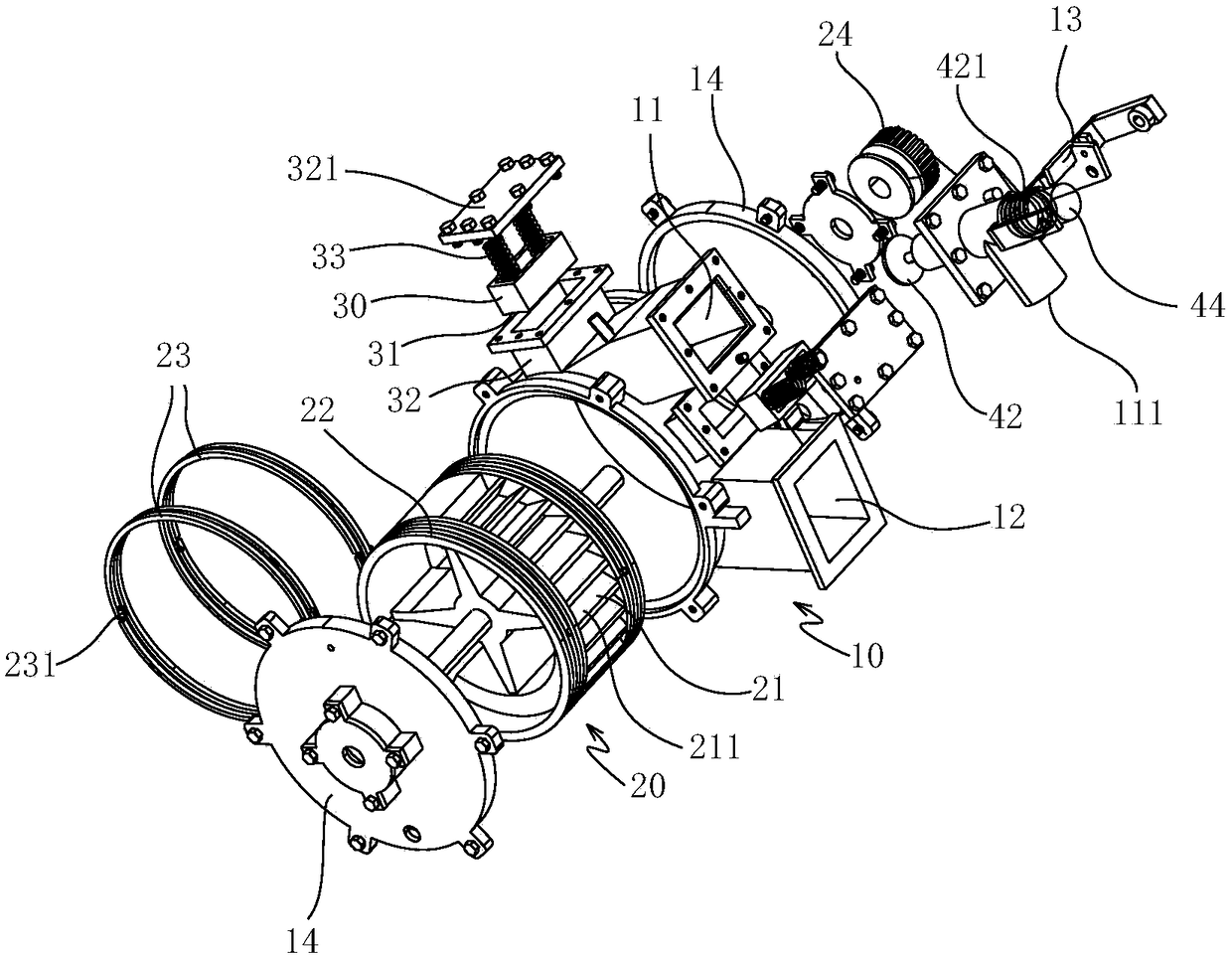
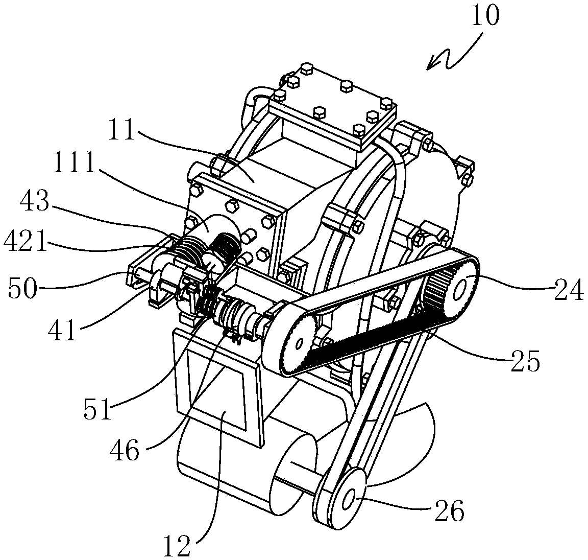
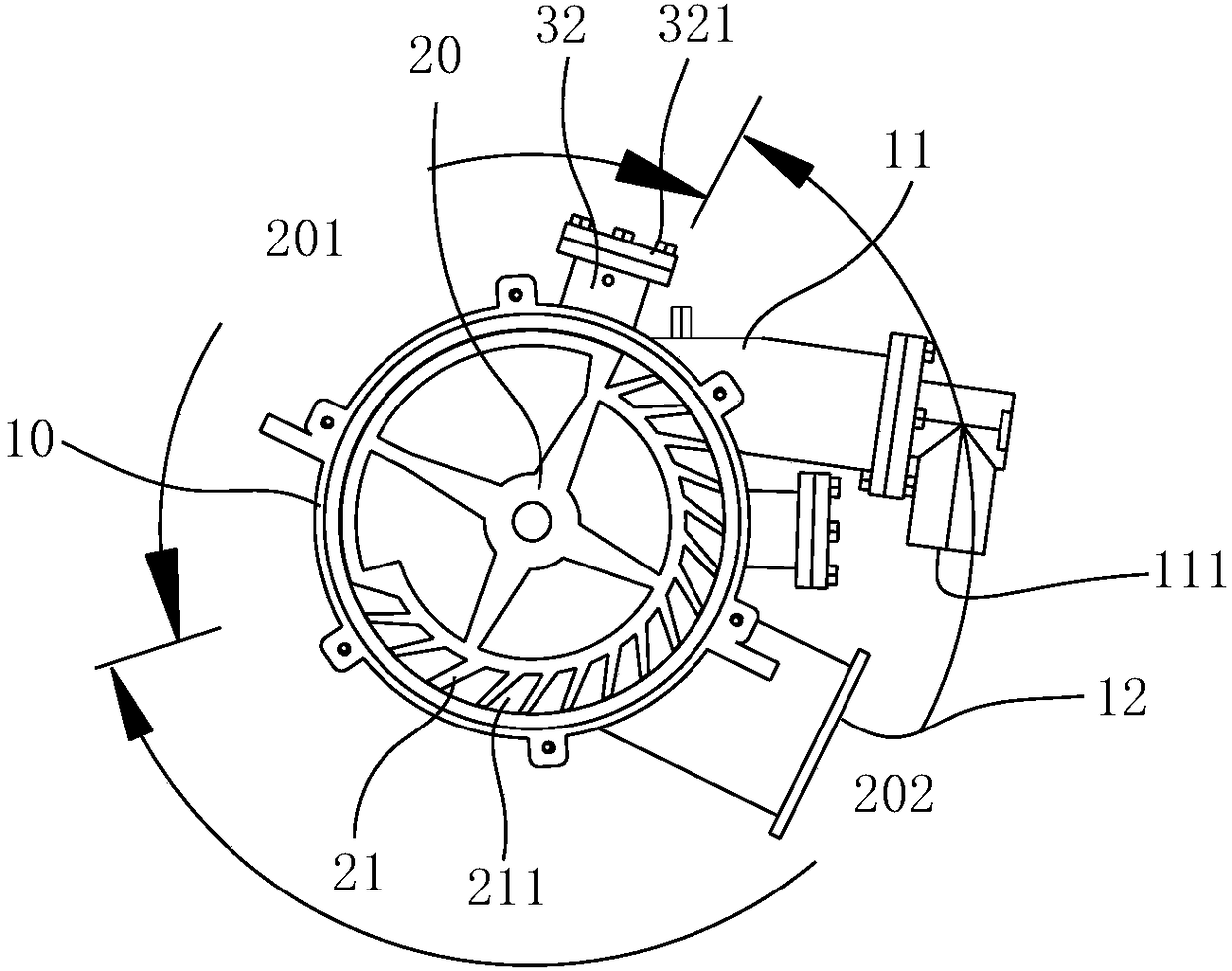
[0029] combine figure 1 with image 3 with Figure 4 , the rotary engine includes an engine block 10, a rotary wheel 20 is arranged in the cylinder block 10, a combustion chamber 11 and an exhaust pipe 12 are arranged on the cylinder block 10, and a fuel injection unit and an ignition unit are arranged in the combustion chamber 11. unit, the combustion chamber 11 is also provided with an air intake pipe 111, the air intake pipe 111 communicates with the combustion chamber 11 and is filled with compressed gas, the runner 20 is cylindrical as a whole, and the outer wall of the runner 20 is provided with multiple blades 21. The blades 21 are strip-shaped and the length direction is arranged along the axial direction of the runner 20. The chamber e...


PUM


Abstract

The invention relates to an air inlet mechanism of a rotating wheel type engine. The air inlet mechanism comprises a rotating wheel arranged in a cylinder body, a combustion cavity and an air exhaust pipe are arranged on the cylinder body, an air inlet pipe is arranged on the combustion cavity, a timing wheel is arranged at the end of a rotating shaft of the rotating wheel, the timing wheel is connected with an input wheel through a timing belt, the input wheel is connected with an input shaft, a first cam is arranged on the input shaft, and the first cam is in an abut fit with the end of a valve rod; and the valve rod and the combustion cavity are in opening or closing fit, the end of the input shaft is connected with a driven shaft through an engage and disengage unit, the first cam is arranged on the driven shaft, a first electromagnetic coil is arranged on the valve rod, a first iron block matched with the first electromagnetic coil is arranged in front of the end of the valve rod, disengagement of the engage and disengage unit corresponds to separation of the driven shaft and the input shaft, and disengage of the engage and disengage unit corresponds to electrifying of the first electromagnetic coil. According to the air supply structure, the manner of air supply to the combustion cavity can be switched according to needs, stretching out and drawing back of the valve rod can be accurately adjusted, the precise air inlet aim is achieved, and therefore the oil saving effect is achieved.

Description

technical field [0001] The invention relates to the technical field of engines, in particular to an intake mechanism of a rotary engine. Background technique [0002] Most of the engines currently used are piston engines, and some engines are also rotary engines. The combustion chamber and the air compression process of the piston engine are carried out in a cylinder body. Spark plugs, intake and exhaust valves and fuel injection nozzles are arranged in the cylinder body. An instant explosion is generated, thereby pushing the piston to work. After the work is burned, the exhaust gas needs to be pushed out by the piston. Due to the limited cross-sectional area of ​​the cylinder block, the cylinder block of the intake valve and exhaust valve is very crowded, which affects the intake and exhaust effects. Now the speed of the engine is getting faster and faster, and the speed is exchanged for torque, and there are many rotating parts, such as the crankshaft, connecting rod, pis...

Claims


Application Information

Patent Timeline
Patent Type & Authority Patents(China)
IPC IPC(8): F02B53/08
CPCF02B53/08Y02T10/12
Inventor 侯春景
Owner 侯春景
Why Eureka
Try Eureka