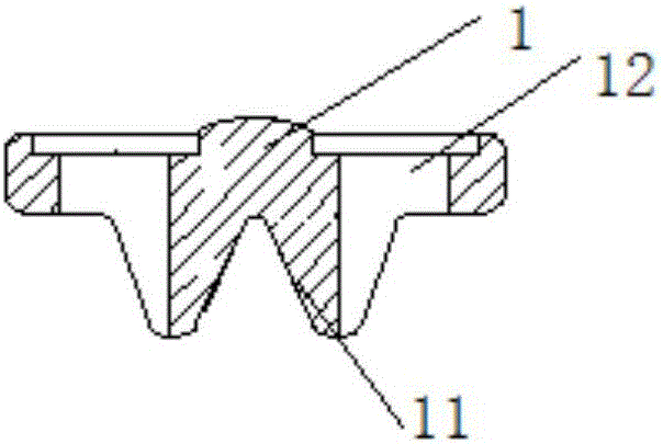
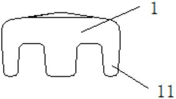
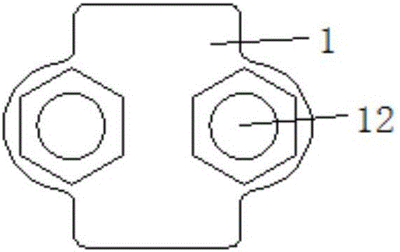
Steel cable grip

A steel wire rope clip and angle technology, which is applied in the direction of transmission elements or pulley ropes or cables, textile cables, belts/chains/gears, etc., can solve the problems of easy broken bones or damage of steel wire ropes, and achieve performance reduction and firmness Clamping and the effect of prolonging the service life

Active Publication Date: 2016-07-20
STATE GRID SHANDONG ELECTRIC POWER +1
View PDF6 Cites 5 Cited by
  • Summary
  • Abstract
  • Description
  • Claims
  • Application Information

AI Technical Summary

Problems solved by technology

[0005] The technical problem to be solved by the present invention lies in the problem that the steel wire rope clamped by chain buckles in the prior art is easy to break or be damaged. Bone or damaged wire rope clips

Method used


Image

  • Steel cable grip
  • Steel cable grip
  • Steel cable grip

Examples


Embodiment Construction

[0040] The technical solutions of the present invention will be clearly and completely described below in conjunction with the accompanying drawings. Apparently, the described embodiments are some of the embodiments of the present invention, but not all of them. Based on the embodiments of the present invention, all other embodiments obtained by persons of ordinary skill in the art without making creative efforts belong to the protection scope of the present invention.

[0041] In the description of the present invention, it should be noted that unless otherwise specified and limited, the terms "installation", "connection" and "connection" should be understood in a broad sense, for example, it can be a fixed connection or a detachable connection. Connected, or integrally connected; it can be mechanically connected or electrically connected; it can be directly connected or indirectly connected through an intermediary, and it can be the internal communication of two components. ...


PUM


Abstract

The invention discloses a steel cable grip. The steel cable grip comprises a grip head, a grip base and a connector, wherein at least two rows of grip head bulges are arranged on the grip head, grip head grooves are formed between the two adjacent grip head bulges in the same row, and first clamping surfaces are formed on the surfaces, facing the grip head bulges in the adjacent rows, of the grip head bulges; at least two rows, being the same with that of the grip head bulges, of grip base bulges are arranged on the grip base, grip base grooves are formed between the two adjacent grip base bulges in the same row, and second clamping surfaces are formed on the surfaces, facing the grip base bulges in the adjacent rows, of the grip base bulges; when the grip head is abutted with the grip base, the same rows of grip head bulges are embedded in the corresponding rows of grip base grooves, the same rows of grip base bulges are embedded in the corresponding rows of grip head grooves, and a clamping hole is formed through the cooperation of the first clamping surfaces on the two adjacent rows of grip head bulges and the second clamping surfaces on the two adjacent rows of the grip base bulges; and the cross section area of the clamping hole formed through the cooperation of the first clamping surfaces and the second clamping surfaces is gradually reduced in the abutting process.

Description

technical field [0001] The invention relates to a wire rope clamp, which belongs to the technical field of wire clamp fixation. Background technique [0002] Wire rope clips can also be called wire rope clips, wire reels, wire clips, etc. They are mainly used for connecting and fixing wire ropes, and can be widely used in hoisting operations. The most common one is a U-shaped clip. For example, in an overhead line, the grounding downconductor of each cement pole is connected to the lightning conductor at the rod head through a U-shaped clip. In actual use, the contact area between the U-shaped clip and the steel wire rope is not large, so that the friction force between the steel wire rope and the U-shaped clip is small, and the steel wire rope is easy to slide or come out by vibration. [0003] The prior art, such as the Chinese patent document whose publication number is CN203906663U, discloses a wire rope interlock buckle, including a base, U-shaped bolts and nuts, the u...

Claims


Application Information

Patent Timeline
Patent Type & Authority Applications(China)
IPC IPC(8): F16G11/05
CPCF16G11/05
Inventor 赵晶郝宗鸣
Owner STATE GRID SHANDONG ELECTRIC POWER
Why Eureka
Try Eureka