LED lighting equipment having wireless communication function

A LED lighting and wireless communication technology, applied in lighting and heating equipment, lighting devices, lighting devices, etc., can solve the problems of signal dead angle, lamp head short circuit, affecting the working efficiency of radio frequency antenna, etc., achieve small power attenuation, prolong service life, The effect of strong voltage shock resistance

Active Publication Date: 2016-07-20
CHENGDU CENTURY PHOTOSYNTHESIS TECH
View PDF8 Cites 7 Cited by
  • Summary
  • Abstract
  • Description
  • Claims
  • Application Information

AI Technical Summary

Problems solved by technology

However, the radio frequency antenna of this patent can only transmit or receive radio frequency signals within a limited range of angles. In actual use, there are many kinds of lamp placement positions. There are signal dead spots in the area
Moreover, the radio frequency antenna is set at the non-reflecting part of the reflector, which is easy to short circuit with the lamp head, posing a safety hazard
In addition, the RF antenna is set on the reflector close to the light source, and the light source will dissipate heat, which will affect the working efficiency of the RF antenna

Method used


Image

  • LED lighting equipment having wireless communication function
  • LED lighting equipment having wireless communication function
  • LED lighting equipment having wireless communication function

Examples


Embodiment 1

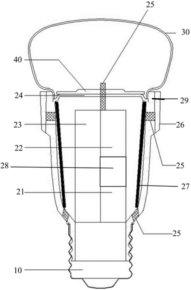
[0045] The present invention provides an LED lighting device with wireless communication function, such as figure 1 As shown, it includes a lamp holder 10 , a lamp housing 20 , a lamp shade 30 , an integrated circuit board, a communication module 22 and an LED light source module 40 .

[0046] Such as figure 2 As shown, the integrated circuit board, the communication module and the LED light source module 40 are arranged in the lamp housing 20 . It should be noted that the LED lighting equipment with wireless communication function under this embodiment 1 does not include figure 2 The outer casing 26 in the middle only includes the lamp housing 20 .

[0047] The lamp housing 20 is connected to the lamp cap 10 and the lampshade 30 respectively. The lamp housing 20 is made of high thermal conductivity plastic with a thermal conductivity of 10-20 W / mk, and the lamp housing 20 is also used as a radiator. A communication module 22 having a wireless relay function is connected...

Embodiment 2

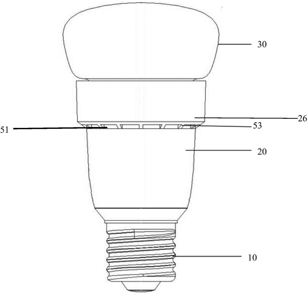
[0057] This embodiment only describes the part of the implementation manner that is different from that of the embodiment 1, and the part of the implementation manner that is the same will not be described again. Compared with the embodiment 1, the embodiment 2 adds an outer casing 26 outside the lamp housing.

[0058] Such as figure 2 The outer shell structure shown. On the outer side of the lamp housing 20 close to the end of the LED light source module 40 , an outer housing 26 with a longitudinal dimension significantly smaller than the lamp housing is sheathed to surround the lamp housing. There is enough space between the outer casing 26 and the lamp housing 20 to accommodate the antenna and allow air convection at both ends of the outer casing 26, so that the antenna disposed on the outer surface of the lamp housing is always in a dry environment.

[0059] When the LED lighting equipment is working, the temperature of the lamp housing is higher than the indoor tempera...

Embodiment 3

[0066] The difference between this embodiment 3 and embodiment 2 is that, as Figure 6 or Figure 7 As shown, the outer casing 26 is a detachable ring-shaped cover structure. The size of the outer casing of the ring-shaped cover structure is sufficient to surround multiple antennas arranged on the surface of the lamp housing. Moreover, the outer shell is provided with a plurality of through holes for forming air convection between the outer shell and the lamp housing to promote the air flow between the outer shell 26 and the lamp housing 20 and speed up the heat dissipation of the lamp housing. The outer casing 26 is detachably sleeved on the outside of the lamp housing 20 in a threaded connection or snap connection manner.

[0067] Corresponding threads are respectively provided on the outer shell 26 and the lamp housing 20 , and the outer shell 26 and the lamp housing 20 are sheathed together in a detachable manner. Alternatively, bayonets and buckles are respectively pro...


PUM


Abstract

LED lighting equipment having a wireless communication function at least comprises a lamp housing (20), a communication module (22) and an LED light source module (40) and is characterized in that the communication module having a wireless relaying function is connected with multiple antennae, and the multiple antennae are arranged inside the lamp housing or on the outer surface of the lamp housing in a space diversity manner. The LED lighting equipment is wide in wireless signal coverage and can realize no-dead-corner wireless signal coverage in an indoor area where the lighting equipment is mounted; besides, the antennae, transmitting signals, of the equipment are arranged in a space formed by the lamp housing and an outer-layer housing and can be protected by the outer-layer housing, so that damage caused by the external environment to the antennae can be prevented, and the quality of the wireless signals cannot be affected. Meanwhile, the antennae are arranged on the surface of the lamp housing capable of transferring heat, so that the antennae are located in the dry environment all the time, and the influence caused by environment moisture on the service life of the antennae is avoided.

Description

technical field [0001] The invention relates to the field of LED lighting, in particular to the field of LED lighting with wireless communication function. Background technique [0002] LED light sources and lamps have been widely used in indoor lighting areas, such as homes, hotels, offices, and other public areas. In addition to lighting needs in these areas, there are also communication needs for wireless Internet access. Although wireless devices have been deployed in the above-mentioned areas, due to comprehensive issues such as the difficulty of installation locations, beautiful decoration, power supply, and the cost of China Unicom’s backbone network, and There are problems such as not getting complete signal coverage indoors, and the number of device connections. [0003] Now in the market to solve the problem of "wireless dead spots", that is, the problem of insufficient coverage of wireless signals indoors, and the problem of insufficient number of APs (wireless a...

Claims


Application Information

Patent Timeline
Patent Type & Authority Applications(China)
IPC IPC(8): F21S2/00F21V33/00F21V15/02F21V3/00F21V29/71H01Q1/22F21Y101/02
Inventor 张祠瑞毛茂郑剑锋王振
Owner CHENGDU CENTURY PHOTOSYNTHESIS TECH
Why Eureka
Try Eureka