Liquid photothermic conversion solar thermal collector

A solar collector and heat conversion technology, applied in the field of solar energy utilization, can solve problems such as excessive energy consumption, cumbersome additional facilities and operations, and achieve the effects of reducing heat dissipation loss, improving receiving efficiency, and prolonging service life

Inactive Publication Date: 2016-07-20
吴跃军
View PDF8 Cites 0 Cited by
  • Summary
  • Abstract
  • Description
  • Claims
  • Application Information

AI Technical Summary

Problems solved by technology

Complicated additional facilities and operations, excessive energy consumption are the inevitable results of the existing product structure

Method used


Image

  • Liquid photothermic conversion solar thermal collector

Examples


Embodiment Construction

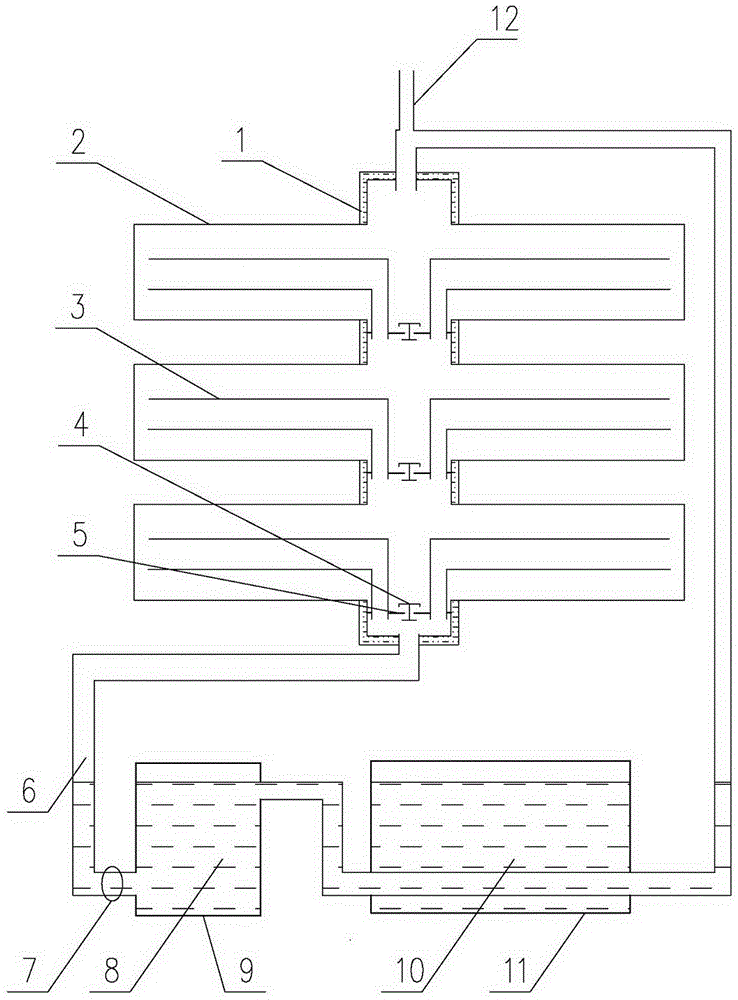
[0014] The liquid light-to-heat conversion solar heat collector includes a vacuum tube connection box 1, a vacuum heat collection tube 2, a liquid pipeline 6 and a pipeline pump 7, a plurality of vacuum heat collection tubes 2 are connected to the vacuum tube connection box 1, and a liquid pipeline 6 is connected to the vacuum tube connection box 1. There is a liquid medium 8 in the circulation pipeline, and the pipeline pump 7 in the liquid pipeline 6 is the power of the liquid circulation; an exhaust port 12 is arranged above the vacuum tube connection box 1, and the vacuum heat collecting tube 2 is a tube A transparent vacuum tube without coating on the wall, the liquid medium 8 is a black liquid, and the liquid medium 8 in the embodiment adopts water-soluble carbon black water. A convection water pipe 3 is arranged in the vacuum heat collecting pipe 2, and the water inlet of the convection water pipe 3 is located in the vacuum tube connection box 1. There is a sealing baffl...


PUM


Abstract

Disclosed is a liquid photothermic conversion solar thermal collector. The liquid photothermic conversion solar thermal collector comprises a vacuum pipe connection box, vacuum thermal collection pipes, a liquid pipeline and a pipeline pump. The multiple vacuum thermal collection pipes communicate with the vacuum pipe connection box. The liquid pipeline is connected with the two ends of the vacuum pipe connection box to form a circulation pipeline. A liquid medium is contained in the circulation pipeline. The pipeline pump in the liquid pipeline is the power for liquid circulation. An exhaust port is formed in the upper portion of the vacuum pipe connection box. The vacuum thermal collection pipes of the liquid photothermic conversion solar thermal collector are transparent vacuum pipes. The liquid medium is black liquid. The liquid photothermic conversion solar thermal collector only works in sunshine, a temperature controlled switch makes the pipeline pump rotate during work, the vacuum pipe connection box is filled with the liquid medium, the liquid medium enters indoors after being heated, and water in an indoor hot water storage tank is heated. When sunshine does not exist, the liquid medium retreats indoors completely, and all outdoor pipelines are drained emptily, so that the possibility of frost damage is avoided. When heating is not needed in summer, work is stopped, all the pipelines are drained emptily. The vacuum pipes are transparent, so that the inside temperature rise range is small, and the possibility of bask damage is avoided.

Description

1. Technical field [0001] The invention belongs to the technical field of solar energy utilization, and in particular relates to a heat collector of a civil solar heat storage device. 2. Background technology [0002] Currently used solar collectors, the solar vacuum tubes are all coated vacuum tubes, relying on the heat generated by sunlight shining on the coating of the tube wall to heat the water in the tube. The water in this kind of coated vacuum tube is not allowed to be emptied. Once the water is emptied, the temperature inside the tube will be too high (above 200 degrees Celsius), which will cause the sealing rubber pad to age and leak. It is easy to cause the vacuum tube to burst, and these defects seriously affect the service life of the product. Due to the water stored in the tubes of the existing solar vacuum tubes, in the cold north, it is easy to freeze the tubes during continuous cloudy days in winter. Most of them need to add heating cables to heat the tubes...

Claims


Application Information

Patent Timeline
Patent Type & Authority Applications(China)
IPC IPC(8): F24J2/24F24J2/30F24J2/34F24J2/46F24S10/30F24S10/70
CPCF24S10/30F24S10/742F24S40/60F24S60/30F24S80/00F24S80/20Y02E10/44
Inventor 吴跃军
Owner 吴跃军
Why Eureka
Try Eureka