Monitoring and adjusting device and method for grating misadjustment in vacuum compression chamber

A technology of a vacuum compression chamber and an adjustment device, which is applied to measurement devices, optical instrument testing, and optical performance testing, etc., can solve problems such as limited offset, low precision, and complex structure, so as to avoid coupling problems, improve use efficiency, simple structure

Active Publication Date: 2018-10-02
SHANGHAI INST OF OPTICS & FINE MECHANICS CHINESE ACAD OF SCI
View PDF6 Cites 0 Cited by
  • Summary
  • Abstract
  • Description
  • Claims
  • Application Information

AI Technical Summary

Problems solved by technology

[0004] 1. The structure is complex (this adds more unstable sources of interference to the remote monitoring and adjustment of the vacuum chamber compressor);
[0005] 2. The accuracy is not high (it cannot meet the quality requirements of the output beam of the femtosecond laser system);
[0006] 3. The amount of misalignment that can be monitored is limited (it can only monitor whether the grating pairs are parallel to each other, which cannot be applied to the 12 degrees of freedom misalignment state of two pairs of grating pairs in the vacuum chamber);
[0007] 4. The monitoring optical path is not separated from the main optical path (when the main optical path in the compression chamber is in use, there must not be any irrelevant components in the optical path that affect the quality of beam compression)

Method used


Image

  • Monitoring and adjusting device and method for grating misadjustment in vacuum compression chamber
  • Monitoring and adjusting device and method for grating misadjustment in vacuum compression chamber
  • Monitoring and adjusting device and method for grating misadjustment in vacuum compression chamber

Examples


Embodiment Construction

[0035] The present invention will be further described below in conjunction with the embodiments and accompanying drawings, but the protection scope of the present invention should not be limited thereby.

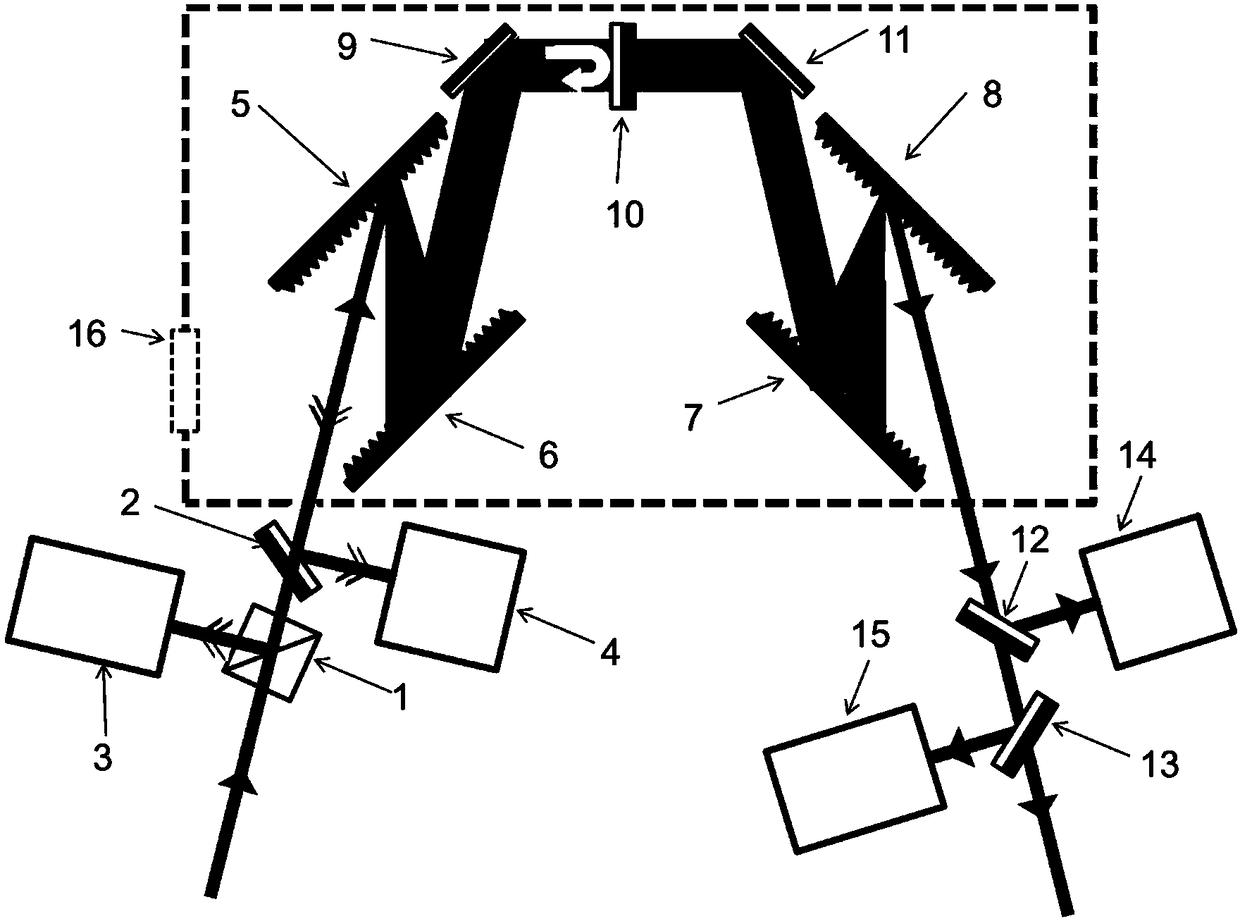
[0036] see first figure 1 , figure 1 It is a schematic diagram of the overall structure of the vacuum compression chamber grating misalignment monitoring and adjusting device of the present invention. The device consists of:

[0037] Dichroic prism, first half mirror, first far-field detection system, first autocorrelator, third half mirror, fourth half mirror, second far-field detection system, second autocorrelator, A double-pass single-parallel grating pair compressor composed of the first grating, the second grating, the third grating, and the fourth grating, and the first plane mirror and the second half-anti-half placed between the second grating and the third grating The lens and the second plane mirror, the double-pass single-parallel grating pair compressor are ...


PUM


Abstract

Provided is a grating offset monitoring and adjusting device in a vacuum compression chamber of a high-power pw system. A light beam passes a light splitting prism and is then input to a far-field detection system for calibration, and the light splitting prism is rotated after calibration. The light beam passes a single-pass double parallel grating pair compressor structure in certain incident angle; a semi-reflection semi-transmission lens between the two grating pairs is used for beam splitting; a reflected light beam returns along an original path, and is input to an autocorrelation instrument and the far-field detection system which is composed of a Fabry-Perot interferometer, an achromatic lens, a microscopic object lens and a CCD; a transmitted light beam passes one grating pair, and is then input to the autocorrelation instrument and the far-field detection system; and each grating is controlled by a stepping motor to rotate along the 3D angular direction. The grating offset monitoring adjusting device and method are characterized in that 1) the structure is simple; 2) offset of the four gratings at any dimensional angle is allowed; 3) a monitoring optical path is separated from a main optical path; 4) adjustment steps are automatic and 5) the precision is high.

Description

technical field [0001] The present invention is a monitoring and adjusting device and adjusting method for grating misadjustment in a vacuum compression chamber in a high-energy petawatt system, which belongs to the field of high-power ultrashort pulse lasers, and is mainly used to ensure the ultrashort pulse laser beam emitted by the high-energy petawatt system quality. Background technique [0002] In actual engineering, in order to eliminate unwanted nonlinear optical effects and ensure the quality of the output beam, the compressor is usually placed in the vacuum compression chamber, due to the instability of the grating support frame motor system, vibration and air flow during the vacuum pumping process As well as long-time use intervals, the grating will inevitably deviate from the ideal position originally set, that is, misalignment will occur, which will cause spectral components to be misaligned in space, resulting in residual angular dispersion. For a large-apertu...

Claims


Application Information

Patent Timeline
Patent Type & Authority Patents(China)
IPC IPC(8): G01M11/02
CPCG01M11/0271
Inventor 朱健强夏素秋
Owner SHANGHAI INST OF OPTICS & FINE MECHANICS CHINESE ACAD OF SCI
Why Eureka
Try Eureka