Fiber laser beam quality measurement method based on photodetector and ccd camera

A photodetector and beam quality technology, applied in the direction of testing optical performance, etc., can solve the problems of complex implementation, low precision, limited application scope, etc., to achieve the effect of convenient operation, easy optical path, simple and correct principle

Active Publication Date: 2018-08-07
NAT UNIV OF DEFENSE TECH
View PDF4 Cites 0 Cited by
  • Summary
  • Abstract
  • Description
  • Claims
  • Application Information

AI Technical Summary

Problems solved by technology

The three-point method and the two-point method are more convenient to measure, but the accuracy is not high; the hyperbola fitting method performs hyperbola fitting by measuring multiple points (usually the far field and the near field should measure at least 5 effective points each), so the accuracy Higher, but the implementation is complicated, usually with the help of related precision instruments
but the M 2 Due to the limited resolution of the CCD and the fixed focal length of the conversion lens, the factor measuring instrument is severely limited in its scope of application. For the measurement of fundamental mode Gaussian beams, it can only be used to accurately measure beams with a beam waist width less than 5mm [" M 2 -200 / 200s-FWUsers Guide", 2009, Ophir-Spiricon Inc. Document No: 11382]

Method used


Image

  • Fiber laser beam quality measurement method based on photodetector and ccd camera
  • Fiber laser beam quality measurement method based on photodetector and ccd camera
  • Fiber laser beam quality measurement method based on photodetector and ccd camera

Examples


Embodiment Construction

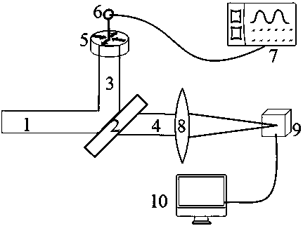
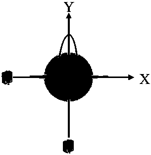
[0043] as attached figure 1 As shown, first adjust the optical axis of the measured beam 1 to the level, put the beam splitter 2 in the optical path, and divide the measured beam into two parts: the reflected beam 3 and the transmitted beam 4, which are used to measure the near field and far field of the beam respectively. . For the measurement of the near field of the beam, we use the photodetector 6 placed on the three-dimensional adjustment platform 5 with a spiral micrometer for measurement. The photodetector 6 can convert the detected light intensity information into voltage information, which can be displayed in real time by the oscilloscope 7, and the voltage value displayed by the oscilloscope 7 can be equivalent to the light intensity value. The specific test method is attached figure 2 shown. By adjusting the screw micrometer in the X direction of 5, the photodetector can be placed at different positions of the measured beam along the X direction passing through...


PUM


Abstract

The invention relates to a fiber laser beam quality measurement method base on a photoelectric detector and a CCD camera. The method comprises: an optical axis of a measured light beam is adjusted to be in a horizontal state, and a beam splitter is arranged at an optical path and thus the measured light beam is divided into two parts that are used for measuring a near field and a far field of the light beam. On the basis of measurement of the near field and the far field of the measured light beam as well as a related data analysis, a near field width and a far field width of the light beam are calculated, so that light beam quality M <2> x and light beam quality M <2>y at a corresponding direction are obtained by calculation. An M<2> factor expression based on near field and far field light intensity distribution of a beam is deduced in theory, so that a defect that the existing M<2> factor measuring instrument can not evaluate the large-size fiber laser beam quality easily can be overcome. The provided fiber laser beam quality measurement method is suitable for fiber laser beam quality measurement including a few of high order modes and some cut fiber laser beam quality measurement.

Description

technical field [0001] The invention relates to a method for measuring the quality of an optical fiber laser beam, in particular to a method for measuring the quality of an optical fiber laser beam based on a photodetector and a CCD camera. Background technique [0002] Beam quality is a very important index in the practical application of laser, and it is generally considered to evaluate the characteristics of laser beam from the aspect of quality. At present, there are many methods for evaluating the quality of laser beams, such as M 2 factor, β Factors, Strehlbi, etc. [Feng Guoying, Zhou Shouhuan, "Discussion on Comprehensive Evaluation of Laser Beam Quality", China Laser, 36, 1643-1653 (2009)]. In the 1990s, A. E. Siegman proposed to use M 2 factor to evaluate beam quality. M 2 The factor is defined as the ratio of the product of the beam waist width of the actual beam and its far-field divergence angle to the corresponding product of the ideal beam. It is also th...

Claims


Application Information

Patent Timeline
Patent Type & Authority Patents(China)
IPC IPC(8): G01M11/02
CPCG01M11/02
Inventor 支冬陶汝茂马阎星司磊吴武明王小林陈子伦周朴许晓军陈金宝刘泽金
Owner NAT UNIV OF DEFENSE TECH
Why Eureka
Try Eureka