A Crack Detection Method of Steel Beam Based on Image Processing

A crack detection and image processing technology, applied in the field of fault diagnosis technology and signal processing analysis, can solve problems such as low efficiency, effective detection of difficult steel beams, and long time consumption

Active Publication Date: 2019-04-09
KUNMING UNIV OF SCI & TECH +1
View PDF4 Cites 0 Cited by
  • Summary
  • Abstract
  • Description
  • Claims
  • Application Information

AI Technical Summary

Problems solved by technology

[0006] Based on the above problems, the present invention provides a steel beam crack detection method based on image processing. When the guide rail on the top of the production line is subjected to upward or downward extrusion force and stress accumulation during the operation of the hanger roller, damage and fracture occur frequently At present, it solves the problem that the workshop staff can only rely on visual inspection to find cracks, the detection workload is heavy, the efficiency is low, and the time is long. Other non-destructive testing techniques are also difficult to effectively detect steel beams.

Method used


Image

  • A Crack Detection Method of Steel Beam Based on Image Processing
  • A Crack Detection Method of Steel Beam Based on Image Processing
  • A Crack Detection Method of Steel Beam Based on Image Processing

Examples


Embodiment 1

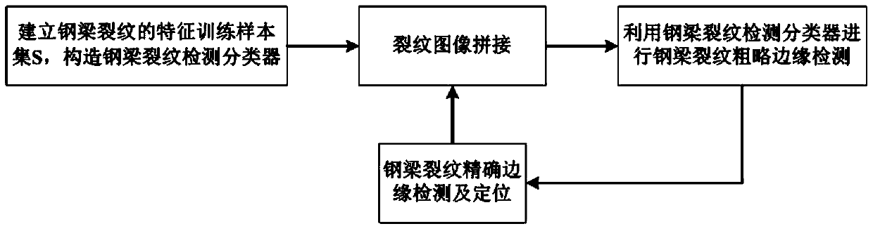
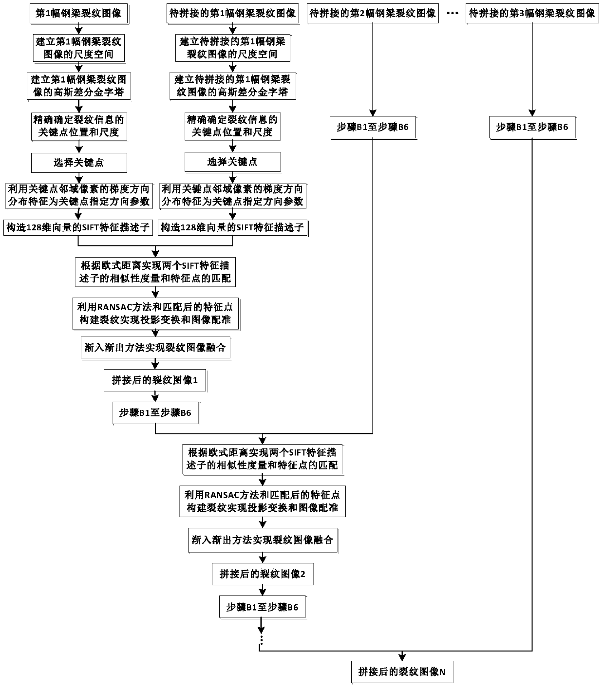
[0050] Embodiment 1: as Figure 1-10 As shown, a steel beam crack detection method based on image processing, first establishes a feature training sample set of steel beam cracks, and makes a Ground Truth set of sample images, and establishes a steel beam crack detection classifier based on structured random forest; then Splice the crack images in each time period in the collected images; use the generated steel beam crack detection classifier to perform rough edge detection of steel beam cracks on the spliced ​​crack images, and obtain rough edge detection results; finally, rough edge detection As a result, accurate crack screening and positioning are carried out.

[0051] The specific steps of the steel beam crack detection method based on image processing are as follows:

[0052] Step1. First extract the steel beam crack image, establish the feature training sample set of the steel beam crack, and make the Ground Truth set of the sample image, together constitute the train...

Embodiment 2

[0077] Embodiment 2: as Figure 1-10 As shown, a steel beam crack detection method based on image processing, the concrete steps of the steel beam crack detection method based on image processing are as follows:

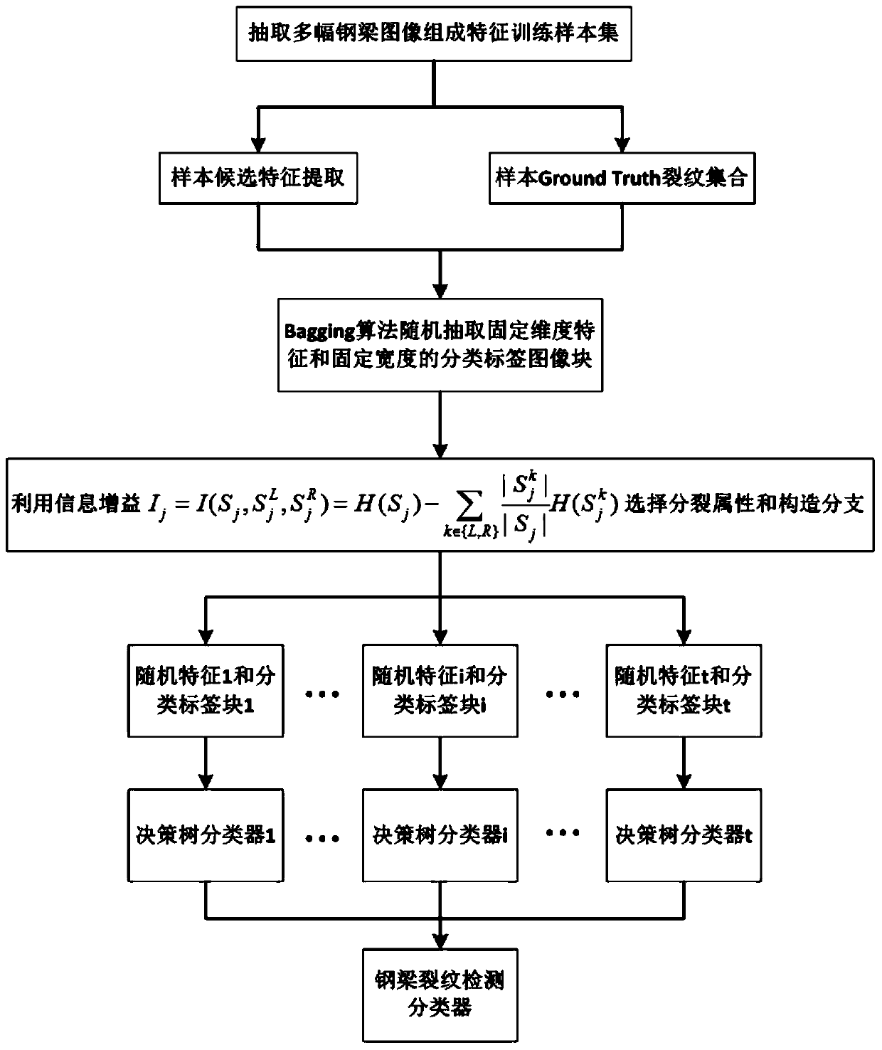
[0078] A. First extract the steel beam crack image, establish a standard 6m square steel beam crack feature training sample set, and make a Ground Truth set of sample images to form a training set S based on the steel beam crack image; secondly, establish a structured random forest The steel beam crack detection classifier h(x,θ j ), the flow chart of constructing the crack detection classifier is as follows figure 2 As shown, by establishing the training set S of node j j ∈X×Y, establish h(x,θ j ) in the random variable θ j The forest model that can maximize the information gain makes the output of the steel beam crack detection classifier a discrete value;

[0079] In the step A, the main steps of constructing the steel beam crack detection classifier are as ...


PUM


Abstract

The invention relates to a steel beam crack detection method based on image processing, which belongs to the field of fault diagnosis technology and signal processing and analysis technology. The invention comprises the steps of: first establishing a feature training sample set of steel beam cracks, and making a Ground Truth set of sample images, and establishing a steel beam crack detection classifier based on a structured random forest; The crack images are spliced; use the generated steel beam crack detection classifier to perform rough edge detection of steel beam cracks on the spliced ​​crack images, and obtain rough edge detection results; finally, perform accurate crack screening and positioning on the rough edge detection results. The invention uses the trained steel beam crack detection classifier to efficiently, quickly and accurately extract the crack information existing in the square steel beam, so as to realize timely and rapid troubleshooting, improve the economic benefits of the factory and protect the personal safety of the staff. Safety.

Description

technical field [0001] The invention relates to a steel beam crack detection method based on image processing, which belongs to the field of fault diagnosis technology and signal processing and analysis technology. Background technique [0002] Once cracks appear on the surface of the steel beams used by industries and enterprises, it will cause great economic losses and serious personal safety problems, especially the top guide rails in the production line. The lower extrusion component and stress accumulation will lead to frequent failure and fracture. At present, workshop staff can only rely on visual inspection to find cracks, which is heavy workload, low efficiency, and time-consuming. Therefore, an effective automatic detection method is urgently needed. [0003] At present, the non-destructive testing techniques commonly used in steel structures include macroscopic inspection, ultrasonic, magnetic particle, penetration, stress-strain testing, etc., but it is difficu...

Claims


Application Information

Patent Timeline
Patent Type & Authority Patents(China)
IPC IPC(8): G06K9/46G06K9/62G06T5/50G01N21/88
CPCG06T5/50G01N21/8851G01N2021/8887G06T2207/30108G06V10/443G06V10/44G06F18/2411G06F18/241
Inventor 伍星王森柳小勤伞红军张印辉蔡正刘畅刘韬
Owner KUNMING UNIV OF SCI & TECH
Why Eureka
Try Eureka