
Large-scale wind dispensing system reactive power compensation method

A static reactive power compensation, large-scale technology, applied in the field of electric power, can solve problems such as economic loss, wind farm voltage drop, automatic voltage adjustment cannot be performed in time, and achieve the effect of ensuring safe and stable operation

Inactive Publication Date: 2016-07-20
STATE GRID CORP OF CHINA +1
View PDF3 Cites 0 Cited by
  • Summary
  • Abstract
  • Description
  • Claims
  • Application Information

AI Technical Summary

Problems solved by technology

Especially when a large-scale wind farm is at the end of the power grid and has no load, the voltage support is relatively weak. After a system failure, the voltage of the wind farm may drop severely, causing a large number of wind turbines to go off-grid due to low voltage. , because the control strategy of the reactive power compensation device in the wind farm is not perfect enough, the automatic adjustment of the voltage cannot be performed in time, and the reactive power compensation device supporting the system voltage and reactive power loss input is still in the state of input when the wind power in the wind power collection station is large, and a large amount of surplus The capacitive reactive power compensation device is still running on the grid, causing the system voltage to rise significantly, which in turn causes a large number of wind turbines to go off the grid due to high voltage
[0004] The power system is a complex dynamic system, any inaccurate equipment action behavior or substandard performance may cause serious consequences, and even cause huge economic losses. Therefore, only relying on fixed-capacity capacitors and reactance The reactive power compensation technology of the large-scale wind power transmission system must meet the operating requirements of various operating modes in the actual operating environment of the actual power system

Method used


Image

  • Large-scale wind dispensing system reactive power compensation method

Examples


Embodiment Construction

[0014] The following will clearly and completely describe the technical solutions in the embodiments of the present invention with reference to the accompanying drawings in the embodiments of the present invention. Obviously, the described embodiments are only some, not all, embodiments of the present invention. Based on the embodiments of the present invention, all other embodiments obtained by persons of ordinary skill in the art without making creative efforts belong to the protection scope of the present invention.

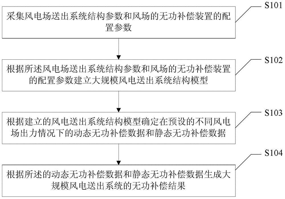
[0015] Such as figure 1 As shown, the present invention provides a reactive power compensation method for a large-scale wind power transmission system, the method includes:

[0016] Step S101, collect the structural parameters of the wind farm sending system and the configuration parameters of the reactive power compensation device of the wind farm;

[0017] Acquisition of structural parameters of the wind farm transmission system includes: wind farm wind tur...


PUM


Abstract

The present invention provides a large-scale wind dispensing system reactive power compensation method. The method includes the steps of collecting a structure parameter of a wind farm dispensing system and a configuration parameter of a reactive power compensation apparatus of a wind farm; establishing a large-scale wind dispensing system structure model according to the structure parameter of the wind farm dispensing system and the configuration parameter of the reactive power compensation apparatus of the wind farm; determining dynamic reactive power compensation data and static reactive power compensation data under conditions of different preset wind farm outputs according to the established wind dispensing system structure model; and generating a reactive power compensation result of the large-scale wind dispensing system according to the dynamic reactive power compensation data and the static reactive power compensation data. According to the large-scale wind dispensing system reactive power compensation technology based on dynamic operation sequence optimization, problems of difficulties of reactive power compensation and voltage stability after access of the large-scale wind dispensing system in the power grid are solved, and the large-scale wind remote dispensing system is ensured to run safely and stably.

Description

technical field [0001] The invention relates to electric power technology, in particular to a reactive power compensation method for a large-scale wind power transmission system. Background technique [0002] At present, the development of wind energy resources in my country has entered a stage of rapid development, and the main characteristics of my country's wind power development are large-scale wind power bases and distance from off-load centers, forming a mode of long-distance wind power transmission and access to the grid. Due to the randomness of wind power generation, Volatility, intermittent, unpredictable and uncontrollable characteristics, so connecting wind power to the grid will inevitably have a certain impact on the operation of the grid. [0003] In the case of large-scale wind power connected to the grid, due to factors such as wind power fluctuations and reactive power characteristics of wind turbines, the voltage stability of the system has become the prima...

Claims


Application Information

Patent Timeline
Patent Type & Authority Applications(China)
IPC IPC(8): H02J3/18
CPCY02E10/76Y02E40/30
Inventor 梁玉枝李善颖金海峰吴涛王丰谢欢李长宇姚谦曹天植
Owner STATE GRID CORP OF CHINA
Learn More