Switch power driving chip and silicon controlled rectifier dimmer LED drive circuit

A switching power supply and drive chip technology, applied in the field of constant current drive, can solve the problems of risk, maximum output current fluctuation, etc.

Active Publication Date: 2016-07-20
SHENZHEN SUNMOON MICROELECTRONICS
View PDF10 Cites 5 Cited by
  • Summary
  • Abstract
  • Description
  • Claims
  • Application Information

AI Technical Summary

Problems solved by technology

[0011] The purpose of the present invention is to provide a switching power supply drive chip and a thyristor dimming LED drive circuit, aiming to solve the problem tha...

Method used


Image

  • Switch power driving chip and silicon controlled rectifier dimmer LED drive circuit
  • Switch power driving chip and silicon controlled rectifier dimmer LED drive circuit
  • Switch power driving chip and silicon controlled rectifier dimmer LED drive circuit

Examples


Embodiment Construction

[0028] In order to make the object, technical solution and advantages of the present invention clearer, the present invention will be further described in detail below in conjunction with the accompanying drawings and embodiments. It should be understood that the specific embodiments described here are only used to explain the present invention, not to limit the present invention.

[0029] In order to illustrate the technical solutions of the present invention, specific examples are used below to illustrate.

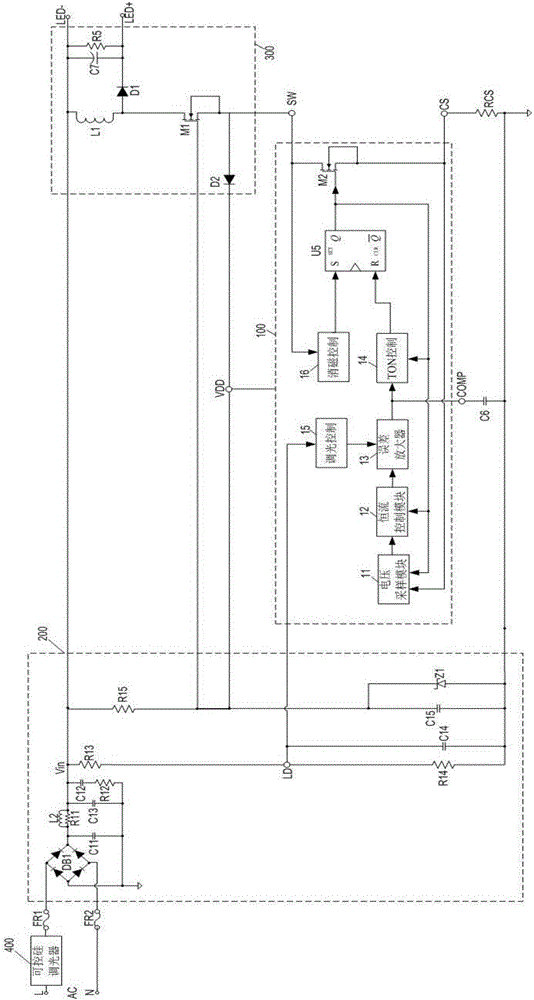
[0030] An embodiment of the present invention is a switching power supply constant current drive chip 100, please refer to figure 1 , connected to the input stage rectifier filter circuit 200 and the output stage circuit 300, the input rectifier filter circuit 200 is connected to the thyristor dimmer 400, the input rectifier filter circuit 200 receives the phase-cut voltage output by the thyristor dimmer 400, and The phase-cutting voltage is rectified into a DC voltage,...


PUM


Abstract

The invention belongs to the technical field of constant current driving, and provides a switch power driving circuit and a silicon controlled rectifier dimmer LED drive circuit. A switch power driving chip is connected with an input-level rectification filter circuit and an output-level circuit, The input-level rectification filter circuit is connected with a silicon controlled rectifier dimmer. The switch power driving chip comprises a dimmer control module, a voltage sampling module, a constant current control module, an error amplifier, conduction time control module, a demagnetization control module, a trigger and a switch member. The silicon controlled rectifier dimmer conducts tangential processing on a wire mesh, and the brightness of a lighting lamp is changed accordingly according to the tangential angle. The input referential voltage of an in-phase input end of the error amplifier is changed to change the current passing through the LED lamp and to further change the brightness of the LED lamp and achieving silicon controlled rectifier dimming purpose. The maximal output current does not fluctuate with the wire mesh and output voltage. The dimming scope is wide, and the cost performance is high.

Description

technical field [0001] The invention belongs to the technical field of constant current driving, and in particular relates to a switching power supply driving chip and a thyristor dimming LED driving circuit. Background technique [0002] Since human beings realize that we must do everything possible to save energy and reduce emissions in order to solve the urgent problem of atmospheric warming, how to reduce lighting power consumption has become an important issue on the agenda, because lighting power consumption accounts for 20% of total energy consumption. As a new generation of green lighting source, high-brightness light-emitting diode (Light Emitting Diode) has the advantages of saving energy by more than 5 times than incandescent lamps, and about twice as energy-saving as fluorescent lamps and energy-saving lamps, and does not contain mercury like fluorescent lamps and energy-saving lamps. . If you can also use dimming to save energy, it is also a very important mean...

Claims


Application Information

Patent Timeline
IPC IPC(8): H05B33/08H05B44/00
CPCH05B45/10H05B45/37Y02B20/30
Inventor 李照华林道明于井亮黄赖长
Owner SHENZHEN SUNMOON MICROELECTRONICS
Why Eureka
Try Eureka