LED drive circuit

A technology of LED driving and driving current, applied in the field of driving circuits, can solve the problems of unbalance, low utilization rate of LED, unbalanced utilization rate of LED, etc.

Active Publication Date: 2016-07-20
SILERGY SEMICON TECH (HANGZHOU) CO LTD
View PDF4 Cites 2 Cited by
  • Summary
  • Abstract
  • Description
  • Claims
  • Application Information

AI Technical Summary

Problems solved by technology

Seoul Semiconductor has proposed a sequential multi-level LED (light-emitting diode) light string structure control strategy. The basic structure of the LED light string is as follows: figure 1 As shown, the advantage of this working mode is that the control is simple, and there is no problem of video flickering in any LED, but the LED utilization rate is unbalanced. For example, when the switch Sa is turned on, LEDLa is always emitting light; when the switch Sb is turned on, LEDLa and Lb are always emitting light; when switches Sa and Sb are turned off, LEDLa, Lb and Lc are always emitting light. It can be seen that the utilization rate of LEDLa is high, but the utilization rate of LEDLb and Lc is low, which may affect the service life of the entire system
Therefore, the unreasonable structural design of the load LED will lead to low or unbalanced LED utilization, which will affect the service life of the entire system

Method used


Image

  • LED drive circuit
  • LED drive circuit
  • LED drive circuit

Examples


Embodiment 1

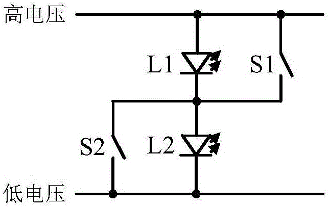
[0126] In this example, if image 3 As shown, the LED array includes two LEDL1, L2 and two switches S1, S2, the two LEDs are respectively the first LEDL1 and the second LEDL2, the cathode of the first LEDL1 and the second LEDL2 connected to the positive pole, the positive pole of the first LEDL1 and the negative pole of the second LEDL2 are respectively connected to the output voltage v o The high and low voltage terminals are connected, the two switches are the first switch S1 and the second switch S2 respectively, and the first switch S1 and the second switch S2 are respectively connected in parallel with the first LEDL1 and the second LEDL2, so The LED structure control circuit is used to control the on-off of the two switches S1 and S2.

[0127] In this embodiment, the first voltage value is the minimum voltage level, the third voltage value is the maximum voltage level, the first current value is the maximum current, and the third current value is the minimum current. O...

Embodiment 2

[0135] Compared with the technical solution in the first embodiment, this embodiment is different in steps 4 and 5 in the LED array and its driving method, and the rest of the technical features are the same as those in the first embodiment, which will not be repeated here.

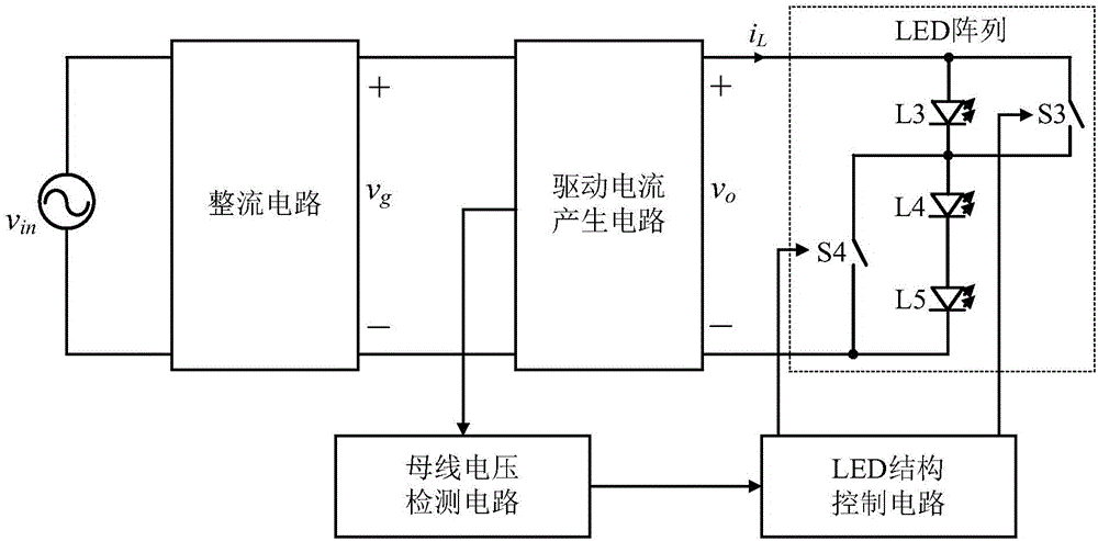
[0136] In this example, if Figure 4 and Figure 5 As shown, the LED array includes three LEDL3, L4, L5 and two switches S3, S4, the three LEDs are respectively the third LEDL3, the fourth LEDL4 and the fifth LEDL5, the negative electrode of the third LEDL3 is connected to the The positive pole of the fourth LEDL4 is connected, the negative pole of the fourth LEDL4 is connected to the positive pole of the fifth LEDL5, the positive pole of the third LEDL3 and the negative pole of the fifth LEDL5 are respectively connected to the output voltage v o The high and low voltage terminals are connected, the two switches are respectively the third switch S3 and the fourth switch S4, the third switch S3 is connect...

Embodiment 3

[0144] Compared with the technical solutions in the previous two embodiments, this embodiment is different in steps 4 and 5 in the LED array and its driving method, and the rest of the technical features are the same as those in the previous two embodiments, so it will not be repeated here. repeat.

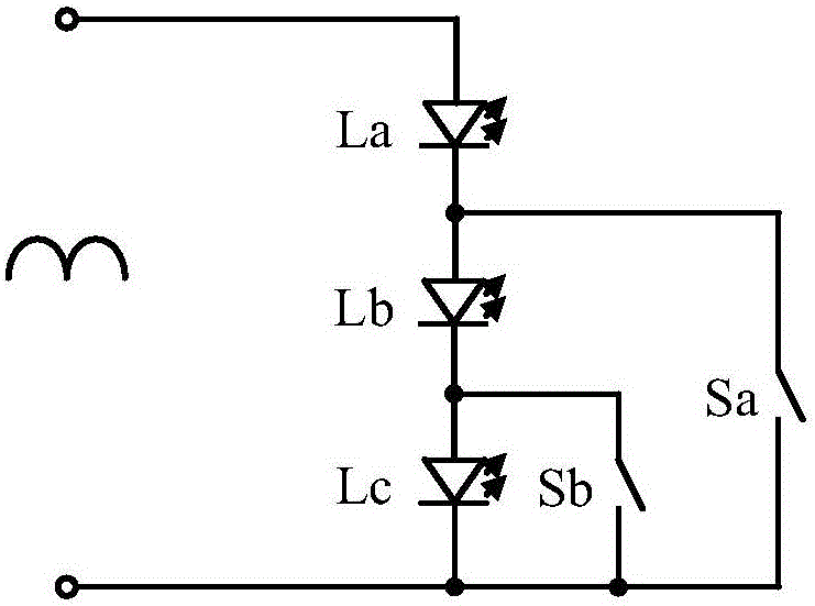
[0145] In this example, if Figure 6 As shown, the LED array includes three LEDL6, L7, L8 and four switches S5, S6, S7, S8, the three LEDs are respectively the sixth LEDL6, the seventh LEDL7 and the eighth LEDL8, the sixth The negative pole of LEDL6 is connected to the positive pole of the seventh LEDL7, the negative pole of the seventh LEDL7 is connected to the positive pole of the eighth LEDL8, the positive pole of the sixth LEDL6 and the negative pole of the eighth LEDL8 are respectively connected to the output voltage v o The high and low voltage terminals are connected, the four switches include the fifth switch S5, the sixth switch S6, the seventh switch S7 and the eighth ...


PUM


Abstract

The present invention provides an LED drive circuit. The LED drive circuit comprises a rectifying circuit, a driving current generation circuit, a bus voltage detection circuit, an LED structure control circuit and an LED array. The LED drive circuit provided by the present invention enables the LED array in the prior art to be changed on the basis of reducing the energy consumption or realizing a high power factor (PF) value, can adjust the utilization rate of each LED by switching the switches, and enables the utilization rates of the LEDs in the LED array to be more uniform, thereby increasing the service life of the LED drive circuit.

Description

[0001] This application is a divisional application with the application number 201310460841.6, the application date is September 29, 2013, and the invention name is "LED drive circuit". technical field [0002] The invention relates to a driving circuit, in particular to an LED driving circuit. Background technique [0003] In order to meet the relevant harmonic standards, the PF (PowerFactor, referred to as power factor) value of the AC-DCLED driver (AC-DC light-emitting diode driver) must be within the specified range. Traditional AC-DC LED drivers are divided into single-stage AC-DC LED drivers and two-stage AC-DC LED drivers. A single-stage AC-DC LED driver can achieve a high PF value by designing reasonable parameters, but the control variables are limited, which is not conducive to optimizing the efficiency of the LED driver, and electrolytic capacitors must be used, which affects the service life of the LED driver and may There is a problem with video flashing. The...

Claims


Application Information

Patent Timeline
Patent Type & Authority Applications(China)
IPC IPC(8): H05B33/08H05B44/00
CPCH05B45/50H05B45/40H05B45/37Y02B20/30
Inventor 赵晨
Owner SILERGY SEMICON TECH (HANGZHOU) CO LTD
Why Eureka
Try Eureka