Metering module for metering AdBlue

A technology of metering device and injection valve, which is applied in exhaust gas treatment, mechanical equipment, engine components, etc., and can solve problems such as the maximum allowable temperature limit of metering module

Active Publication Date: 2016-07-20
ROBERT BOSCH GMBH
View PDF8 Cites 7 Cited by
  • Summary
  • Abstract
  • Description
  • Claims
  • Application Information

AI Technical Summary

Problems solved by technology

Sealing, supporting and / or insulating with elastomers limits the maximum permissible temperature of the metering module

Method used


Image

  • Metering module for metering AdBlue
  • Metering module for metering AdBlue

Examples


Embodiment Construction

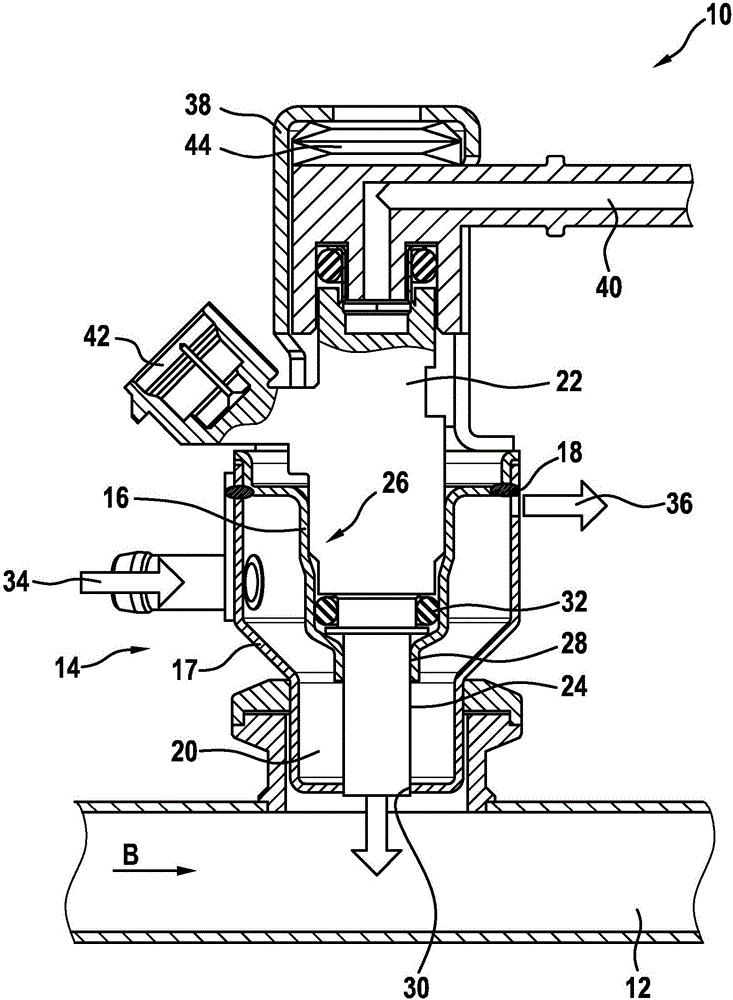
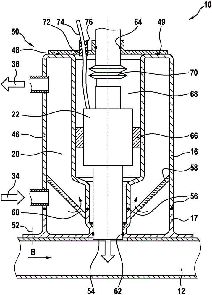
[0024] figure 1 Shown is a metering device 10 which is used in an SCR system for metering reducing agent into an exhaust line 12 , wherein the exhaust gas flow flows in a flow direction B through the exhaust line 12 . The exhaust stream comes from figure 1In an internal combustion engine, not shown, the exhaust pipe 12 adjoins the internal combustion engine on its discharge side. The metering device 10 comprises a base body 14 , which is formed from a first sheet metal 16 and a second sheet metal 17 , which are connected to one another in an abutment region or overlapping region by a soldered connection 18 . The plates 16 and 17 are spaced apart from each other and form an annular cavity 20 . Furthermore, an injection valve 22 , the housing of which is designated 24 , is accommodated in the base body 14 . The contour of the first metal sheet 16 is selected such that an adaptive receptacle 26 for the injection valve 22 is formed. The injection valve 22 forms an abutment reg...


PUM


Abstract

The invention relates to a metering device (10) for introducing a process liquid or auxiliary agent into a flow pipe of an internal combustion engine, in particular for introducing a reducing agent into an exhaust gas pipe (12). The metering device comprises an injection valve (22) and a receiving device (50) comprising a heat sink element (46) and a cover element (48). The injection valve (22) and the receiving device (50) are combined to form a structural unit by means of material bonded connections (62, 64).

Description

technical field [0001] The invention relates to a metering device comprising an injection valve and a receiving device, which are combined to form a structural unit by means of a cohesive connection. Background technique [0002] In known metering devices for liquid reducing agents (known for example from DE 10 2008 041 486 ), a metering module is used which comprises a metering unit for injecting the reducing agent into the exhaust gas region, for example an injection valve, and consists of A holding device or an adapter is received, by means of which the connection to the exhaust system takes place. In order to be able to optimally introduce the reducing agent into the exhaust gas, the metering module must be located as close as possible to the high-temperature exhaust system, wherein temperatures of up to 700° C. can be reached in the exhaust system of internal combustion engines. Due to the high heat input that is forced into the metering module, there is a risk of over...

Claims


Application Information

Patent Timeline
Patent Type & Authority Applications(China)
IPC IPC(8): F01N3/20
CPCF01N3/2066F01N2450/22F01N2610/00F01N2610/02F01N2610/11F01N2610/1453Y02T10/12
Inventor M·穆尔斯特A·克尼特尔G·埃尔索T·克雷埃尔T·蓝克尔J·温克勒C·亨克尔
Owner ROBERT BOSCH GMBH
Why Eureka
Try Eureka