Ring pusher

A technology of a ring pusher and a clamp arm, applied in the field of medical supplies, can solve the problems of easy longitudinal axis rotation of the ring body, difficulty in releasing the ring body, time-consuming and laborious operation, etc., so as to reduce the burden on patients, be convenient to use, and avoid waste of resources. Effect

Active Publication Date: 2017-09-05
张瑞芳
View PDF8 Cites 0 Cited by
  • Summary
  • Abstract
  • Description
  • Claims
  • Application Information

AI Technical Summary

Problems solved by technology

However, the purpose of intrauterine foreign body forceps is mainly to take out IUDs or intrauterine residual bone fragments, etc., and there are 5 deficiencies in the process of pushing IUDs for such surgical instruments: 1. The toothed surfaces of this type of surgical forceps are all flat , while Mirena's hormone storage is a cylindrical structure and polyethylene material, it is easy to squeeze the hormone storage capsule when pushing, resulting in deformation or damage of the part, leakage of hormone drugs, etc.; 2. The clamp head of this type of instrument The length of the bit is 20mm, while the length of Mirena’s ring body is 32mm. The birth control system exceeds the length of the surgical instrument, and there is a risk of uterine perforation during the pushing process; 3. The flat mouth design is prone to vertical axis rotation during the pushing process; 4. Palace The cavity foreign body forceps has no lock design, and the Mirena slips halfway during the pushing process. The doctor cannot use the strength of the wrist but the strength of the arm during the operation, which is time-consuming and laborious to operate; 5. Release the ring body after pushing it in place Difficult, due to the friction between the toothed structure and the ring body, the ring body sticks to the foreign body forceps

Method used


Image

  • Ring pusher
  • Ring pusher
  • Ring pusher

Examples


Embodiment Construction

[0022] The present invention will be further described below in conjunction with the drawings and specific embodiments:

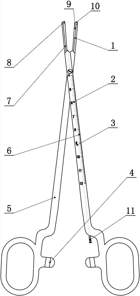
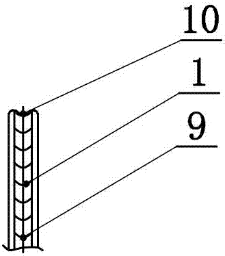
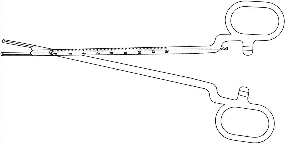
[0023] The invention is like figure 1 , 2 , 3, 4, and 5, a ring pusher, including a left pliers arm 5 and a right pliers arm 3, the left pliers arm 5 and the right pliers arm 3 are hinged, characterized by: the left pliers arm 5 and the right pliers arm 3 The upper end is designed with a right semicircular cover 1 and a left semicircular cover 7, respectively, the left semicircular cover 7 is designed with a left groove 8 at the outer edge of the upper end, and the right semicircular cover 1 is designed with a right groove 10 at the outer edge of the upper end. The right groove 10 is on the same horizontal line. In this embodiment, the left semicircular cover 7 corresponds to the right semicircular cover 1, the left clamp arm 5 and the right semicircular cover 1 are a whole, the right clamp arm 3 and the left semicircular cover 7 are a whole, and the left semi...


PUM


Abstract

The invention provides a ring push device which comprises a left clamp arm and a right clam arm, the left clamp arm is hinged to the right clamp arm, a right semicircular hood and a left semicircular hood are designed on the upper end of the left clamp arm and the upper end of the right clamp arm respectively, a left groove is designed in the outer edge of the upper end of the left semicircular hood, a right groove is designed in the outer edge of the upper end of the right semicircular hood, the left groove and the right groove are formed in the same horizontal line, the left semicircular hood corresponds to the right semicircular hood, the left clamp arm and the right semicircular hood are integrated, the right clamp arm and the left semicircular hood are integrated, and insections are designed on the inner surfaces of the left semicircular hood and the right semicircular hood.

Description

Technical field [0001] The invention relates to a medical article, in particular to a ring pusher. Background technique [0002] In recent years, the application of the levonorgestrel intrauterine birth control system brand name Mirena, or IUS, is relatively mature. 111 countries around the world have approved the use of this birth control system, which is mainly used for contraception, idiopathic menorrhagia, and hormone replacement therapy HRT , And treatment of gynecological diseases such as dysmenorrhea caused by adenomyosis. There are data showing that patients with dysmenorrhea and heavy menstrual flow have a higher probability of levonorgestrel intrauterine contraceptive system shifting and prolapse. On the one hand, patients with a lower birth control system have lower abdominal pain and increased menstrual flow. On the other hand, they worry about contraception failure or interruption of treatment after the birth control system breaks out. With the development of socie...

Claims


Application Information

Patent Timeline
Patent Type & Authority Patents(China)
IPC IPC(8): A61F6/18
CPCA61F6/18
Inventor 张瑞芳靳士英邵莉
Owner 张瑞芳
Why Eureka
Try Eureka