Insulator cleaning robot mechanism

A technology for cleaning robots and cleaning mechanisms, applied to chemical instruments and methods, cleaning methods and utensils, cleaning methods using tools, etc., can solve problems such as low cleaning efficiency and complicated cleaning mechanisms, and achieve flexible and reliable operations and stable movement Reliable, adaptable results

Active Publication Date: 2016-07-27
SHENYANG INST OF AUTOMATION - CHINESE ACAD OF SCI
View PDF7 Cites 4 Cited by
  • Summary
  • Abstract
  • Description
  • Claims
  • Application Information

AI Technical Summary

Problems solved by technology

In terms of research on insulator cleaning robots, Xi’an Electric Power Rectifier Factory has mainly studied the live insulator cleaner for suspended insulators. The operator uses an insulating rod to vertically send the cleaner to the insulator to be cleaned. The cleaner needs to be cleaned by manual operation. The Korean Electric Power Research Institute has developed a crawler-type electrified cleaning mechanism. The cleaning machine is mainly composed of four parts: two half-divided inner rings, two symmetrical half-divided outer rings, connecting devices on the left and right parts, sliding rods and connecting inner and outer rings. Composed of lead screws with rings, the upper and lower surfaces of the insulator can be cleaned, but the cleaning mechanism is complicated and the cleaning efficiency is not high

Method used


Image

  • Insulator cleaning robot mechanism
  • Insulator cleaning robot mechanism
  • Insulator cleaning robot mechanism

Examples


Embodiment Construction

[0026] The present invention will be described in further detail below in conjunction with the accompanying drawings.

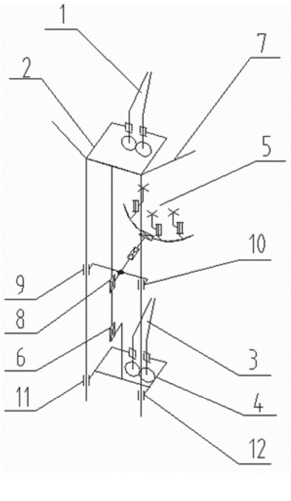
[0027] Such as figure 1 Shown, the present invention comprises upper jaw 1, upper frame 2, lower jaw 3, lower frame 4, cleaning mechanism 5, first movable joint 6, frame 7 and second movable joint 8, wherein upper frame 2 and machine The frame 7 is fixedly connected, and the lower frame 4 is slidably connected with the frame 7 through the seventh moving joint 11 and the eighth moving joint 12 (the way that the slide block cooperates with the guide rail), and the seventh moving joint 11 and the eighth moving joint 12 are placed vertically and are joints for passive movement. The lower frame 4 is connected to the upper frame 2 through the first vertical moving joint 6 , and the upper jaw 1 and the lower jaw 3 are respectively arranged on the upper frame 2 and the lower frame 4 . The cleaning mechanism 5 is connected with the upper frame 2 through the second m...


PUM


Abstract

The invention relates to a mobile robot mechanism, and specifically relates to an insulator cleaning robot mechanism. The insulator cleaning robot mechanism comprises an upper clamping jaw, an upper frame, a lower clamping jaw, a lower frame, a cleaning mechanism, a first mobile joint, a rack and a second mobile joint. The upper frame is connected with the rack, the lower frame is in slip connection with the rack, the lower frame is connected with the upper frame through the first mobile joint which is vertically arranged, the upper clamping jaw is arranged on the upper frame, the lower clamping jaw is arranged on the lower frame, the cleaning mechanism is connected with the upper frame through the second mobile joint which is vertically arranged, the cleaning mechanism is in slip connection with the rack, the relative motion between the upper clamping jaw and the lower clamping jaw is achieved through the first mobile joint, and the cleaning mechanism can move up and down along an insulator chain through the second mobile joint. According to the invention, a peristaltic creeping manner is employed, the insulator cleaning robot mechanism is high in load capacity, steady and reliable in motion, flexible in cleaning work and simple to control, and is not liable to generate the deadlocking phenomenon.

Description

technical field [0001] The invention relates to a mobile robot mechanism, in particular to an insulator cleaning robot mechanism. Background technique [0002] Taking effective measures to prevent large-scale pollution flashover accidents in the power grid and reduce the pollution flashover trip rate is one of the important contents to improve the reliability of power grid power supply. At present, the anti-pollution cleaning of transmission line insulators mainly includes manual power-off cleaning, mechanical live cleaning and Type insulator floor cleaning and charged water flushing, etc. In terms of research on insulator cleaning robots, Xi’an Electric Power Rectifier Factory has mainly studied the live insulator cleaner for suspended insulators. The operator uses an insulating rod to vertically send the cleaner to the insulator to be cleaned. The cleaner needs to be cleaned manually. The Korean Electric Power Research Institute has developed a crawler-type electrified cl...

Claims


Application Information

Patent Timeline
Patent Type & Authority Applications(China)
IPC IPC(8): B08B1/04H02G1/02
Inventor 王洪光常勇景凤仁刘爱华潘新安王林
Owner SHENYANG INST OF AUTOMATION - CHINESE ACAD OF SCI
Why Eureka
Try Eureka