
Plasma cutting machine

A plasma cutting machine and cutting nozzle technology, applied in the direction of plasma welding equipment, welding/cutting auxiliary equipment, auxiliary devices, etc. Effects of operators and environmental operators

Inactive Publication Date: 2016-07-27
ANHUI TECHN COLLEGE OF MECHANICAL & ELECTRICAL ENG
View PDF8 Cites 0 Cited by
  • Summary
  • Abstract
  • Description
  • Claims
  • Application Information

AI Technical Summary

Problems solved by technology

[0002] In the process of realizing the present invention, the inventors have found that the prior art has at least the following problems: since most of the CNC plasma cutting machines used in industrial production, a large amount of smoke and dust will be generated during the start-up and cutting process of the work operation, this part Even if there is an indoor dust removal device for smoke and dust, it cannot be completely removed, and it cannot protect the operator and the working environment well

Method used


Image

  • Plasma cutting machine

Examples


Embodiment Construction

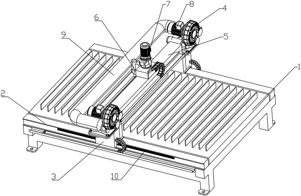
[0020] In order to make the object, technical solution and advantages of the present invention clearer, the implementation manner of the present invention will be further described in detail below in conjunction with the accompanying drawings.

[0021] see figure 1 , a plasma cutting machine having:

[0022] Bed 1;

[0023] There are two rails 2, which are respectively arranged on two opposite sides of the bed 1;

[0024] There are two supporting bases 3, which are respectively arranged on the two rails 2 and can slide on the rails 2;

[0025] A stand 5 is connected to two support bases 3;

[0026] The cutting nozzle 7 is arranged on the support base 3 and can slide on the support base 3 to process the workpiece on the bed 1;

[0027] There are two axial flow fans 4, which are respectively arranged on two supporting bases 3;

[0028] The smoking pipe 9 is U-shaped, the middle part spans the bed 1, and the two ends of the U are respectively connected to the suction ports o...


PUM


Abstract

The invention discloses a plasma cutting machine which comprises a lathe body (1), two rails (2), two supporting seats (3), a rack (5), a cutting nozzle (7), two axial flow fans (4) and a smoke suction pipe (9), wherein the rails (2) are respectively arranged on the two relative sides of the lathe body (1); the supporting seats (3) are respectively arranged on the two rails (2) and can slide on the rails (2); the rack (5) is connected with the two supporting seats (3); the cutting nozzle (7) is arranged on the supporting seats (3) and can slide on the supporting seats (3) to process a workpiece on the lathe body (1); the axial flow fans (4) are respectively arranged on the two supporting seats (3); the smoke suction pipe (9) is U-shaped; the middle part of the smoke suction pipe (9) horizontally crosses the lathe body (1); the two ends of the U-shaped smoke suction pipe (9) are respectively connected at air suction openings of the two axial flow fans (4); and a smoke hole is formed in the position, right opposite to the lathe body (1), of the lower part of the smoke suction pipe (9). According to the plasma cutting machine, residual smoke which is not discharged in the cutting process is absorbed and cleaned, and the function of protecting the environment and operators is achieved.

Description

technical field [0001] The invention belongs to the technical field of industrial production, and in particular relates to a plasma cutting machine. Background technique [0002] In the process of realizing the present invention, the inventors have found that the prior art has at least the following problems: since most of the CNC plasma cutting machines used in industrial production, a large amount of smoke and dust will be generated during the start-up and cutting process of the work operation, this part Even if there is an indoor dust removal device for smoke and dust, it cannot be completely removed, and it cannot protect the operator and the working environment well. Contents of the invention [0003] The technical problem to be solved by the present invention is to provide a plasma cutting machine that absorbs and cleans the residual fume that has not been discharged during the cutting process. [0004] In order to solve the above-mentioned technical problems, the t...

Claims


Application Information

Patent Timeline
Patent Type & Authority Applications(China)
IPC IPC(8): B23K10/00B23K37/00
CPCB23K10/00B23K37/00
Inventor 张帅谋肖传芳张国政王小平周洋洋
Owner ANHUI TECHN COLLEGE OF MECHANICAL & ELECTRICAL ENG
Learn More