Spring loading device of limiting switch assembling machine
A technology of limit switch and assembly machine, which is applied in the direction of electric switch, metal processing, electrical components, etc., can solve the problems of easy defective products, long assembly cycle, high cost, etc., and achieve the effect of reducing production cost and saving labor force
- Summary
- Abstract
- Description
- Claims
- Application Information
AI Technical Summary
Problems solved by technology
Method used
Image

Examples
Embodiment Construction
[0008] The preferred embodiments of the present invention will be described in detail below in conjunction with the accompanying drawings, so that the advantages and features of the invention can be more easily understood by those skilled in the art, so as to define the protection scope of the present invention more clearly.
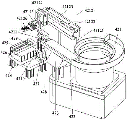
[0009] see figure 1 , the embodiment of the present invention includes:
[0010] A spring feeding device of a limit switch assembly machine, the spring feeding device of the limit switch assembly machine includes a spring vibrating tray 421, a spring linear feeder 422, a spring vibrating device 423, a cylinder bracket 424, a first push-pull Cylinder 425, gear bar 426, synchronous gear 427, gear seat 428, cylinder mounting plate 429, rotating clamping cylinder 4210, magnetic sucker 4211 and transposition manipulator 4212, the discharge port of described spring vibrating material disc 421 is provided with spring straight line The feeder 422, the spring li...
PUM
 Abstract
Description
Claims
Application Information
PatSnap Eureka turns technology decisions into work you can execute. Powered by our Innovation Knowledge Graph, it runs expert workflows across engineering, life sciences, materials and intellectual property. Get your review-ready output in minutes.


