A waste recovery tail water treatment device

A water treatment device and waste technology, which is applied in multi-stage water treatment, water/sewage multi-stage treatment, water/sludge/sewage treatment, etc., to achieve the effect of complete separation, high efficiency and simple structure

Inactive Publication Date: 2018-11-30
晋江市冠兴建材有限责任公司
View PDF6 Cites 0 Cited by
  • Summary
  • Abstract
  • Description
  • Claims
  • Application Information

AI Technical Summary

Problems solved by technology

[0004] In the above-mentioned patents, the tail water coming out of the vibration dehydrator also contains certain sludge and floating matter, which needs further treatment

Method used


Image

  • A waste recovery tail water treatment device
  • A waste recovery tail water treatment device
  • A waste recovery tail water treatment device

Examples


Embodiment Construction

[0055] In order to further explain the technical solution of the present invention, it will be described in detail below in conjunction with the accompanying drawings.

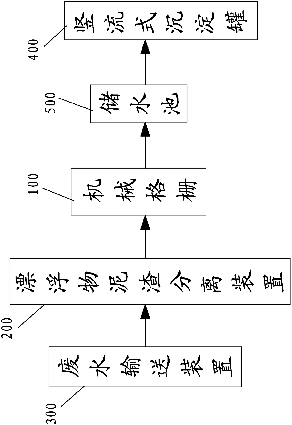
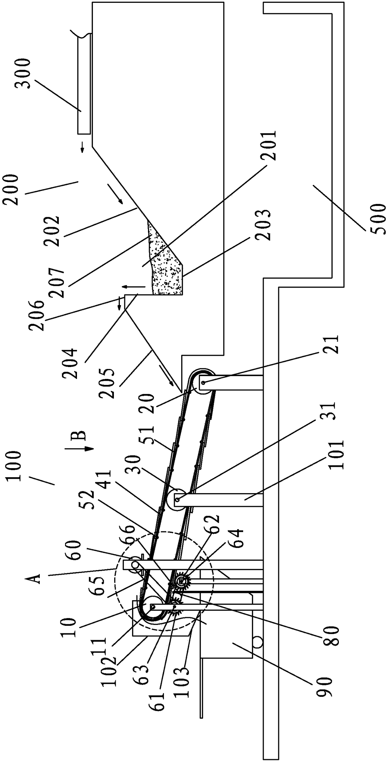
[0056] refer to Figures 1 to 6 , a tail water treatment device for waste recovery, a waste water conveying device 300, a floating matter and slag separating device 200, a mechanical grid 100 and a vertical flow sedimentation tank 400, the outlet end of the waste water conveying device 300 and the floating and slag separating device 200 The water inlet is connected, the water outlet of the floating debris and slag separation device 200 is connected with the water inlet of the mechanical grille 100, and the water outlet of the mechanical grille 100 is connected with the water inlet of the vertical flow sedimentation tank 400. In the embodiment, the water outlet end of the mechanical grill 100 is connected to the water storage tank 500, and the water storage tank 500 is connected to the vertical flow sedimentati...


PUM


Abstract

The invention relates to a device for treating tail water produced by waste recycling; the device comprises a waste water conveying device, a flotage-sludge separation device, a mechanical grid and a vertical flow sedimentation tank, wherein a water outlet end of the waste water conveying device is communicated with a water inlet end of the flotage-sludge separation device, a water outlet end of the flotage-sludge separation device is communicated with a water inlet end of the mechanical grid, and a water outlet end of the mechanical grid is communicated with a water inlet end of the vertical flow sedimentation tank. By adopting the technical scheme of the invention, the flotage-sludge separation device is used for carrying out first stage of separation on sludge, so that the sludge with larger particle sizes can be separated; the mechanical grid is used for carrying out first stage of separation on larger flotage; the vertical flow sedimentation tank is used for carrying out second stage of separation on the sludge and the flotage; therefore, the device is capable of carrying out two-stage separation on the sludge and the flotage, thus more thoroughly and efficiently separating the sludge and the flotage in waste water; the device for treating the tail water produced by waste recycling has a characteristic of being simple in structure; the sludge separated by the device can be directly used in building materials, so that environment-friendly utilization is realized.

Description

technical field [0001] The invention relates to a tail water treatment device for waste recovery. Background technique [0002] Coal slag is waste slag discharged from thermal power plants, industrial and civil boilers and other equipment burning coal. Coal slag is discharged into the environment and seriously pollutes the environment. At present, most of the coal cinders are disposed of by landfill, which will cause secondary pollution. For this reason, people have invented equipment for processing coal slag, but most of the equipment for processing coal slag currently only has magnetic separators, conveyors, and crushers. However, because the crushed material still contains relevant useful metal substances, the quality of recycling is affected because the crushed material is not crushed and screened again, resulting in a waste of resources; in addition, the sand obtained after screening and separation cannot be recycled. Cause resource waste again; Therefore, it is neces...

Claims


Application Information

Patent Timeline
Patent Type & Authority Patents(China)
IPC IPC(8): C02F9/02
CPCC02F9/00C02F2301/08
Inventor 林文革
Owner 晋江市冠兴建材有限责任公司
Why Eureka
Try Eureka