Support arm and excavator

A swing frame and connecting arm technology, which is applied in the field of swing frames and excavators, can solve the problems of shaft sleeve detachment, fracture, low overall strength and bonding strength, etc.

Inactive Publication Date: 2016-07-27
泉州市泉永机械发展有限公司
View PDF2 Cites 8 Cited by
  • Summary
  • Abstract
  • Description
  • Claims
  • Application Information

AI Technical Summary

Problems solved by technology

[0002] As known, the swing frame is connected between the bucket and the bucket oil cylinder, mainly including two front bushings (commonly known as Qianqiu ears), rear bushings (commonly known as Qianqiu arm heads) and connectors, and the two front bushings are coaxially spaced apart. The rear bushing is arranged in parallel with the two front bushings, and the connector is connected between the two front bushings and the rear bushing. Bucket pivot connection; the connecting piece is welded with the front and rear bushings. The existing connecting piece is usually a one-piece casting or welded and assembled by multiple steel plates. The overall strength and bonding strength are low, and it is easy to connect with the shaft Sleeve detachment and breakage

Method used


Image

  • Support arm and excavator
  • Support arm and excavator
  • Support arm and excavator

Examples


Embodiment 1

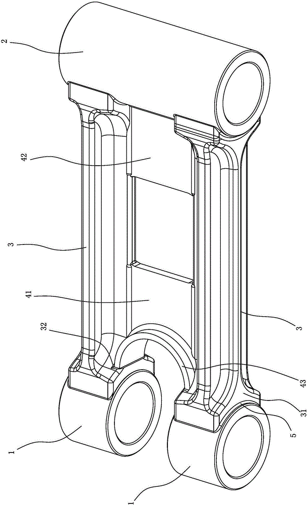
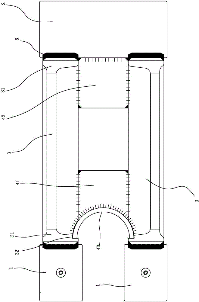
[0024] Embodiment one, with reference to figure 1 , figure 2 , Figure 4 and Figure 5 As shown, a swing frame includes two front bushings 1, a rear bushing 2, two connecting arms 3 and a support.

[0025] The two front bushings 1 are coaxially arranged at intervals, the rear bushing 2 is arranged parallel to the two front bushings 1, and the two connecting arms 3 are respectively welded between the two front bushings 1 and the rear bushing 2, and the supporting parts are welded between the two connecting arms. between arms 3.

[0026] The connecting arm 3 is a forging, and the two ends of the connecting arm 3 are formed with a joint portion 31 that increases and expands. The edge of joint surface 312 forms chamfer 311, and this chamfer 311 and front and rear end bushing 1,2 outer peripheral surfaces form solder filling groove, realizes connecting arm 3 and front and back through the solder 5 that fills in solder filling groove. Welding of end sleeves 1 and 2,

[0027] ...

Embodiment 2

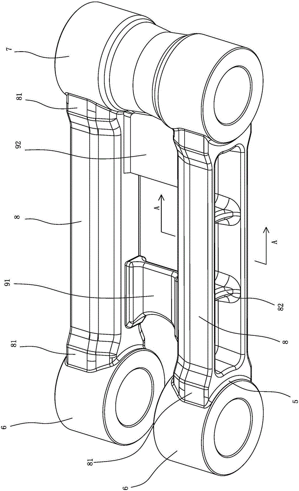
[0029] Embodiment two, refer to image 3 and Figure 6 As shown, a swing frame includes two front bushings 6, rear bushings 7, two connecting arms 8 and support members, the two front bushings 6 are coaxially spaced apart, and the rear bushings 7 are parallel to the two front bushings 6. Arrangement, the two connecting arms 8 are respectively welded between the two front bushings 6 and the rear bushing 7, and the support member is welded between the two connecting arms 8.

[0030] The connecting arm 8 is a forging, and the two ends of the connecting arm 8 are formed with a joint portion 81 that increases and expands. The edge of the surface forms a chamfer 811, and the chamfer 811 and the outer peripheral surfaces of the front and rear end shaft sleeves 6, 7 form a solder filling groove, and the connecting arm 8 and the front and rear end shafts are realized by filling the solder 5 in the solder filling groove. Welding of sets 6 and 7,

[0031] The support includes front an...


PUM


Abstract

The invention discloses a support arm which comprises two front shaft sleeves and a rear shaft sleeve. The two front shaft sleeves are coaxially arranged in a spaced manner. The rear shaft sleeve is parallel and opposite to the two front shaft sleeves. The support arm is characterized by further comprising two connecting arms connected between the two front shaft sleeves and the rear shaft sleeve, and a supporting part connected between the two connecting arms; the connecting arms are forged parts; the two ends of each connecting arm are provided with arc combining faces matched with the outer circumferential face of the corresponding front shaft sleeve and the outer circumferential face of the rear shaft sleeve; the connecting arms are combined with the front shaft sleeves and the rear shaft sleeve in a welded manner; the forged parts are adopted as the connecting arms so that the strength of the connecting arms can be greatly improved; due to combined faces, stress faces between the connecting arms and the shaft sleeves can be improved, and in addition, the combining strength of the connecting arms and the shaft sleeves is improved; and the supporting part is arranged between the two connecting arms so that the integral strength of the support arm can be further improved.

Description

technical field [0001] The invention relates to a swing frame and an excavator. Background technique [0002] As known, the swing frame is connected between the bucket and the bucket oil cylinder, mainly including two front bushings (commonly known as Qianqiu ears), rear bushings (commonly known as Qianqiu arm heads) and connectors, and the two front bushings are coaxially spaced apart. The rear bushing is arranged in parallel with the two front bushings, and the connector is connected between the two front bushings and the rear bushing. Bucket pivot connection; the connecting piece is welded with the front and rear bushings. The existing connecting piece is usually a one-piece casting or welded and assembled by multiple steel plates. The overall strength and bonding strength are low, and it is easy to connect with the shaft Sets detached and broken. Contents of the invention [0003] The object of the present invention is to provide a high-strength swing frame and an ex...

Claims


Application Information

Patent Timeline
Patent Type & Authority Applications(China)
IPC IPC(8): E02F3/36
CPCE02F3/3604
Inventor 刘斌吴永东叶星煅
Owner 泉州市泉永机械发展有限公司
Why Eureka
Try Eureka