a steam turbine

A steam turbine and cylinder technology, applied in mechanical equipment, engine components, machines/engines, etc., can solve the problems of large energy loss, low mechanical efficiency, and less mechanical energy of steam turbines, so as to improve the utilization rate of heat energy, improve mechanical efficiency, The effect of not easy aging and wear

Inactive Publication Date: 2017-06-20
高宏亮
View PDF4 Cites 0 Cited by
  • Summary
  • Abstract
  • Description
  • Claims
  • Application Information

AI Technical Summary

Problems solved by technology

This structure using the windmill principle results in a large energy loss of the steam turbine, so the mechanical efficiency is low
[0006] Another reason for the low mechanical efficiency of the steam turbine is that when the blade blades are impacted by the hot air flow parallel to the axis of the impeller, the heat energy consumed by the fan peak and the fan root of the blade blades in the unit area is equal, and the heat energy produced by them is equal. The mechanical energy is different, the fan peak arm is long, the torque is large, and it generates more mechanical energy; the fan root arm is small, the torque is small, and it generates less mechanical energy
[0007] 2. Low utilization rate of heat energy
[0008] In the existing steam turbine, the moving direction of the hot air flow in the cylinder is parallel to the axis of the impeller, and the hot air flow forms a direct air flow in the cylinder. Because the direct air flow runs in the shortest path in the cylinder, the amount of work done by the hot air flow in the cylinder is small. Therefore, the effective utilization of heat energy is low
[0009] 3. Bearings are prone to aging and wear
To improve the mechanical efficiency, it is necessary to increase the torque of the impeller. Correspondingly, it is necessary to increase the height of the blades on the impeller. As a result, the weight of the impeller itself increases, the load on the bearing increases, and the bearing is prone to aging and wear.

Method used


Image

  • a steam turbine
  • a steam turbine
  • a steam turbine

Examples


Embodiment Construction

[0051] The present invention will be specifically introduced below in conjunction with the accompanying drawings and specific embodiments.

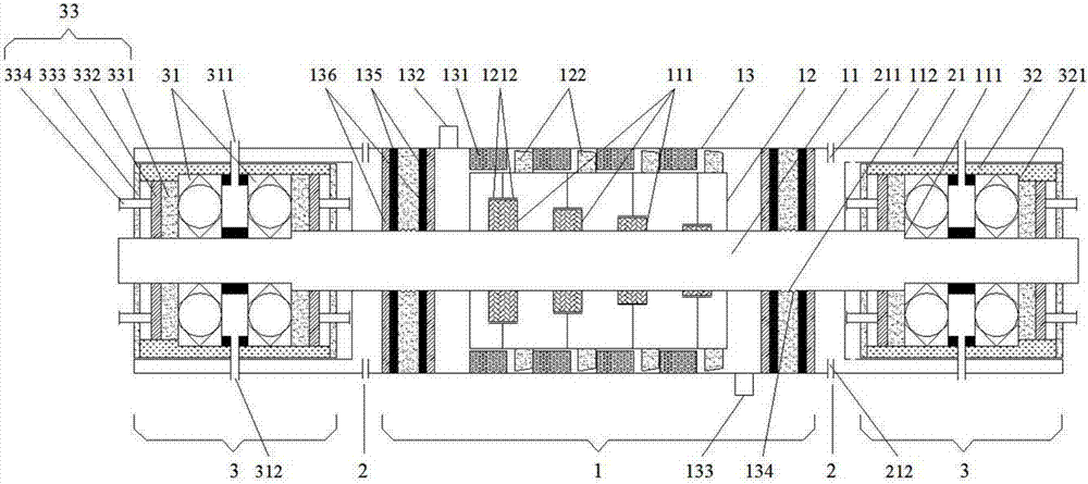
[0052] refer to figure 1 , the present invention has high thermal energy utilization rate and high mechanical efficiency and durable steam turbine, which is cylindrical as a whole, including: cylinder part 1, cooling part 2 and lubricating part 3, wherein, cooling part 2 is located at the two sides of cylinder part 1 At the end, the lubricating part 3 is embedded in the center of the bottom surface of the two cooling parts 2 .

[0053] The structures of the cylinder part 1, the cooling part 2 and the lubricating part 3 will be described in detail below.

[0054] 1. Cylinder

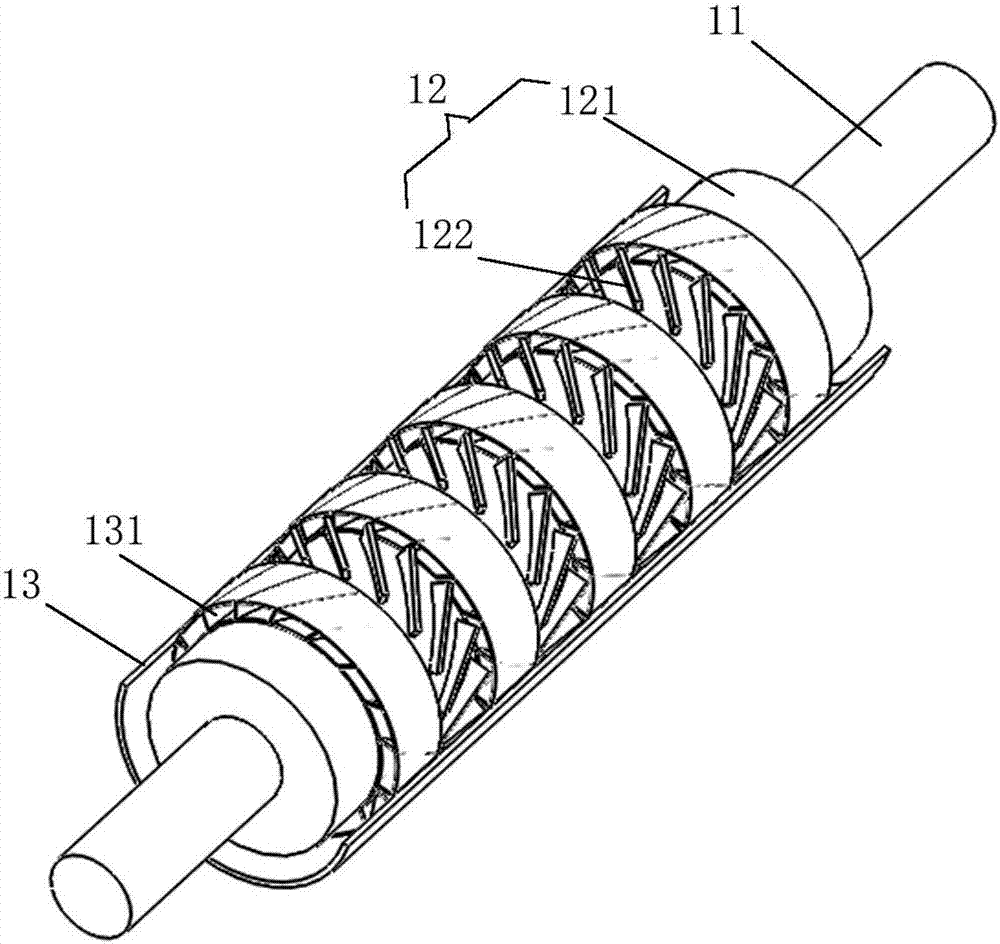
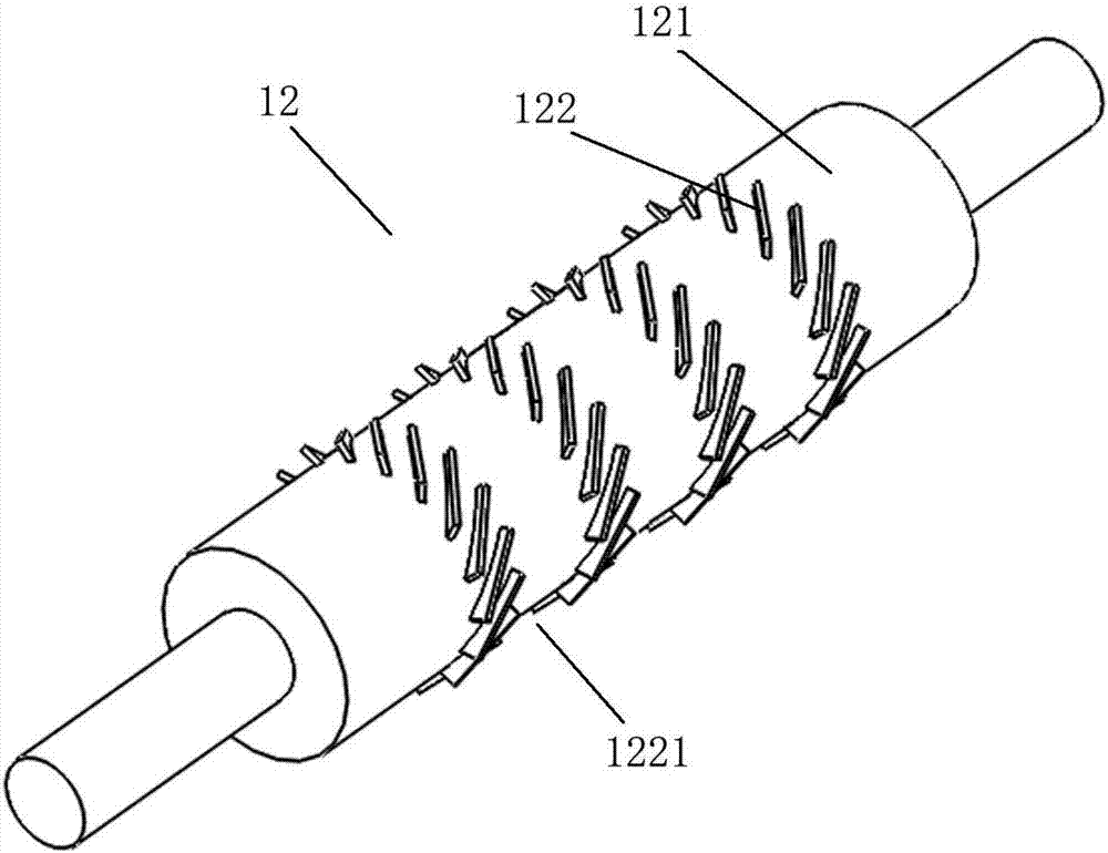
[0055] refer to figure 1 with figure 2 , The cylinder part 1 sequentially includes: a rotating shaft 11 , a hollow impeller 12 and a cylinder 13 from the inside to the outside.

[0056] 1. Shaft

[0057] refer to figure 1 with Figure 5 , the rotating shaft ...


PUM


Abstract

The invention discloses a durable steam turbine with the high heat energy utilization rate and high mechanical efficiency. The steam turbine is cylindrical overall and comprises a cylinder portion, cooling portions and a lubricating portion. The cylinder portion sequentially comprises a rotating shaft, a hollow impeller and a cylinder body from inside to outside. The hollow impeller is composed of a wheel body and wheel plates. The wheel plates are evenly distributed on the circumferential line of the outer wall of the wheel body. The included angle formed between each wheel plate and the axis of the wheel body is larger than 0 degree and smaller than 90 degrees. Direction-variable grids are formed on the inner wall of the cylinder body in the axis direction. The included angle between an air way of each direction-variable grid and the circular bottom face of the cylinder body is larger than 0 degree and smaller than 90 degrees, and the air ways on the direction-variable grids are perpendicular to the wheel plates on the hollow impeller in a one-to-one corresponding manner when the cylinder body is closed. The durable steam turbine has the beneficial effects that the dead weight of the steam turbine is reduced greatly by the adoption of the hollow impeller, and bearings are more durable; and the airflow direction is changed artificially through the direction-variable grids, the heat energy required for maintaining acting can be reduced, the heat energy utilization rate of the steam turbine can be increased, and mechanical energy and mechanical efficiency can be improved.

Description

technical field [0001] The invention relates to a steam turbine, in particular to a durable steam turbine with high thermal energy utilization rate and high mechanical efficiency, which belongs to the mechanical field. Background technique [0002] In the existing steam turbine, the impeller is provided with a large number of vanes, and the volume of the cylinder is equal to the space that the vanes pass in the cylinder during one rotation. The higher the blade, the larger the cylinder volume and the greater the impeller torque, correspondingly, the more heat energy is required to maintain work. [0003] Due to the limitations of structure and technology, the existing steam turbines mainly have the following three problems: [0004] 1. Low mechanical efficiency [0005] In the existing steam turbine, the direction of movement of the hot air in the cylinder is parallel to the axis of the impeller, and the hot air cannot impact the blade plate surface vertically, but the imp...

Claims


Application Information

Patent Timeline
Patent Type & Authority Patents(China)
IPC IPC(8): F01D1/04F01D25/12F01D25/08F01D25/18F01D25/16F01D9/04F01D25/14F01D25/24
CPCF01D1/04F01D9/041F01D25/08F01D25/12F01D25/125F01D25/145F01D25/16F01D25/18F01D25/183F01D25/24
Inventor 高宏亮
Owner 高宏亮
Why Eureka
Try Eureka