
Device for improving internal flow stability of diagonal flow pump

A technology of internal flow and stability, applied to parts, pumps, pump components, etc. of pumping devices used for elastic fluids, can solve the problem of affecting the safety and reliability of the operation of inclined flow pumps, reducing the blade's ability to work on the fluid, and stalling And other issues

Inactive Publication Date: 2016-07-27
JIANGSU UNIV
View PDF6 Cites 1 Cited by
  • Summary
  • Abstract
  • Description
  • Claims
  • Application Information

AI Technical Summary

Problems solved by technology

Diagonal flow pumps tend to cause stall and backflow at the rim of the impeller inlet under small flow conditions, making the flow channel blocked and deflected to the hub area, reducing the work ability of the blades to the fluid; at the same time, the guide The impeller inlet is also prone to rotating stall near the hub, causing backflow. In severe cases, the backflow will expand to the hub of the impeller inlet, thereby affecting the workability of the impeller and increasing the flow loss; due to the influence of the rotating stall and backflow phenomenon, the oblique flow When the pump is running under the condition of small flow, the pressure pulsation is irregular, and the amplitude of the pressure pulsation is greatly improved compared with the design condition, which greatly affects the safety and reliability of the diagonal flow pump operation.

Method used


Image

  • Device for improving internal flow stability of diagonal flow pump
  • Device for improving internal flow stability of diagonal flow pump
  • Device for improving internal flow stability of diagonal flow pump

Examples


Embodiment Construction

[0028] The present invention will be described in further detail below in conjunction with the accompanying drawings and specific embodiments.

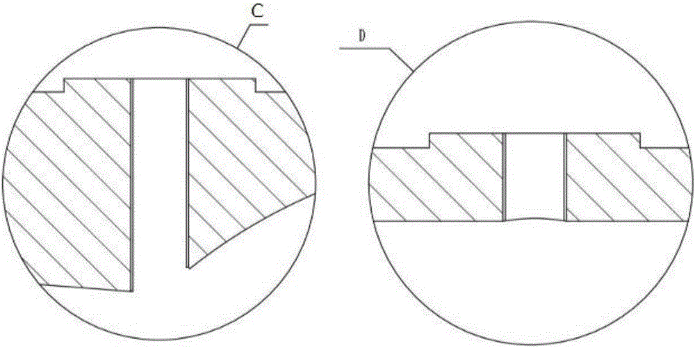
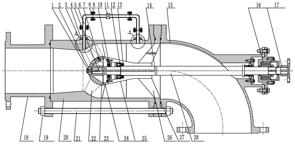
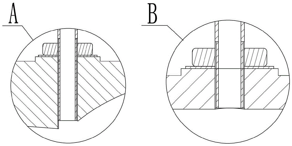
[0029] Depend on figure 1 It can be seen that the diagonal flow pump is composed of (1) hexagon socket head screw, (2) water guide cone, (3) sealing washer, (4) nut, (5) ordinary flat key, (6) conduit (7) cylinder head Screw, (8) flange, (9) bolt, (10) left oil seal of bearing, (11) valve, (12) bearing, (13) right oil seal of bearing, (14) hole, (15) elbow section, ( 16) Rear sealing end cover, (17) Coupling, (18) Inlet section, (19) Hexagonal thick nut, (20) Circular outer cylinder, (21) Pull rod, (22) Blade, (23) Runner Wheel hub, (24) hole, (25) guide vane body, (26) streamlined rib, (27) O-ring, (28) pump shaft. The inlet section (18) is connected and fixed with the circular outer cylinder (20) through the tie rod (21), and the inlet section (18) and the circular outer cylinder (20) are positioned and ensure concentricity throug...


PUM


Abstract

The invention provides a device for improving internal flow stability of a diagonal flow pump. The device comprises an inlet section, a circular outer barrel, guide tubes, check valves, an impeller, guide vanes, a rotating shaft, and other parts, wherein the inlet section is directly connected with the circular outer barrel through flanges; 8 guide tubes are uniformly distributed on the circumference of the circular outer barrel; the part, connected with the impeller and guide vane bodies, of the rotating shaft is hollow; two holes are formed in the positions, corresponding to guide vane body flanges and guide vane inlets, of the rotating shaft; and a hole is formed in the position, near the back inlet side of each guide vane, of a hub. According to the device, under low flow working conditions, the guide vane inlets can easily suffer rotating stall, and when the backflow is severe, the backflow extends to the hub at an outlet of the impeller, so that the work of the impeller to the water body is greatly influenced, and the flow loss is increased; and high-pressure water of guide vane outlets enter the hollow section of the rotating shaft through the holes, and then flows into the guide vane inlets through the holes, so that the static pressure value of the guide vane inlets can be improved, the adverse pressure gradient is reduced, the rotating stall of the guide vanes is inhibited, and the lift and efficiency of the pump are improved.

Description

technical field [0001] The invention relates to a pump type commonly used in large and medium-sized pump stations with low head, large flow rate and wide high-efficiency area, especially related to the improvement of internal flow instability and the "hump" of the head curve under the small flow rate condition of the diagonal flow pump The inhibition of the area expands the application range of the mixed flow pump. Background technique [0002] Diagonal flow pump is a pump type with high specific speed, and its performance is between axial flow pump and centrifugal pump. The hydraulic performance of the centrifugal pump is good, but the structure is complicated; although the axial flow pump has the advantages of simple structure and small footprint, but the high efficiency area is narrow, and the scope of use is relatively narrow; however, the diagonal flow pump has both the axial flow pump and the centrifugal pump. It has the advantages of head change range of 3-30m, head ...

Claims


Application Information

Patent Timeline
IPC IPC(8): F04D29/40F04D29/18
CPCF04D29/403F04D29/18F05D2240/12
Inventor 张德胜刘俊龙耿琳琳石磊陈健
Owner JIANGSU UNIV
Learn More