Guide block for preventing linear displacement blocking of electromechanical actuator

An electromechanical actuator and linear displacement technology, which is applied in the field of guide blocks, can solve the problems of large rolling friction space requirements, loss of function of electromechanical actuators, and difficult processing, etc., to achieve heavy weight, difficult processing, and light weight Effect

Active Publication Date: 2016-07-27
BEIJING RES INST OF PRECISE MECHATRONICS CONTROLS
View PDF6 Cites 1 Cited by
  • Summary
  • Abstract
  • Description
  • Claims
  • Application Information

AI Technical Summary

Problems solved by technology

[0003] The electromechanical servo mechanism converts the alternating rotation of the motor into the linear motion of the screw. In order to control the screw to not rotate, but only to move in a straight line, we need to design a guide in the linear direction. The guide has rolling friction and sliding friction. The friction space is large and the processing is difficult. Because the electromechanical actuators of aviation, spaceflight and aerospace require small space and light weight, there is an urgent need for a guide block that is light in weight, anti-jamming, and easy to process. This invention is a sliding Friction, in the past, the sliding guide block had the phenomenon of seizure or jamming with the lead screw nut. The seizure or jamming would cause the electromechanical actuator to lose its function or even be destroyed. For this reason, an electromechanical actuator was invented to prevent linear Displacement jammed guide blocks to prevent electromechanical actuators from being seized and jammed

Method used


Image

  • Guide block for preventing linear displacement blocking of electromechanical actuator
  • Guide block for preventing linear displacement blocking of electromechanical actuator
  • Guide block for preventing linear displacement blocking of electromechanical actuator

Examples


Embodiment Construction

[0027] In the following, the guide block of the present invention will be described from several aspects with reference to the accompanying drawings. details as follows:

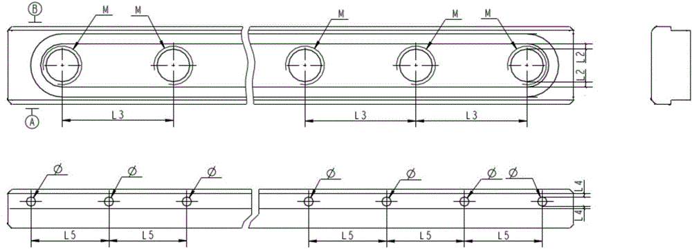
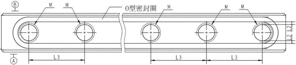
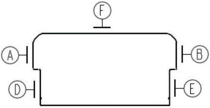
[0028] (1) Design the cross section of the guide block as T-shaped (such as figure 1 , 3 (Shown) to avoid direct collisions with the sharp edges and sharp corners of the lead screw nut guide groove, and prevent the lead screw nut guide groove from colliding with the guide block from generating extra objects and jamming and seizure;

[0029] After repeated, many times, a large number of experiments to summarize: such as Figure 5 As shown, (1) The narrow side of the T-shaped guide block should be smaller than the wide side, and L8 is (0.6~2)mm to determine the width as the best state, which will neither touch sharp corners nor affect the strength. (2) The narrow side should avoid the sharp angle L6=(0.35~0.75)mm to determine the most suitable height.

[0030] The “collision” mentioned above is not an exaggeration. ...


PUM


Abstract

The invention discloses a guide block for preventing linear displacement blocking of an electromechanical actuator. The section of the guide block is T-shaped; the width of the narrow edge of the T-shaped section is 0.6-2mm less than the width of the wide edge; threaded holes are uniformly distributed in the guide block in the length direction; on end of the narrow edge of the T-shaped section is fixed on the inner wall of an electromechanical actuator shell through a screw to ensure that the guide block is located in a guide slot of a lead screw nut; the distance between the upper end face of the nut in the guide slot and the interface between the narrow edge and the wide edge of the T-shaped section is 0.35-0.75mm; the fit clearances between the two end faces of the wide edge of the T-shaped section and the guide slot satisfy 0.01-0.02mm, and the depth of parallelism is 0.01-0.02mm.

Description

Technical field [0001] The patent of the invention relates to a guide block, which is especially suitable for the linear displacement transmission guide of the lead screw in the electromechanical actuator of aviation, aerospace and aerospace. Background technique [0002] The electromechanical servo mechanism is an important flight control mechanism used in aviation, aerospace, aerospace and other aircraft. The electromechanical servo system is developing rapidly, and its application is expanding rapidly. Compared with the hydraulic servo, the electromechanical servo has its outstanding advantages, so in the future The application and development prospects of the company are very broad. [0003] The electromechanical servo mechanism converts the alternating rotation of the motor into the linear motion of the screw. In order to control the screw not to rotate, but only move in a straight line, we must design a linear direction guide, which has rolling friction and sliding friction. ...

Claims


Application Information

Patent Timeline
Patent Type & Authority Applications(China)
IPC IPC(8): F16H25/20F16H25/24
CPCF16H25/20F16H25/2418F16H2025/204
Inventor 侯占林崔佩娟肖翀刘伟王春明
Owner BEIJING RES INST OF PRECISE MECHATRONICS CONTROLS
Why Eureka
Try Eureka