Noise elimination vibration reduction gear

A gear and gear body technology, applied in the direction of gear lubrication/cooling, belts/chains/gears, components with teeth, etc., can solve the problems of surrounding medium disturbance, noise and vibration, and large noise, and achieve novel structure and extended Service life, noise reduction effect

Inactive Publication Date: 2016-07-27
蒙泽喜
View PDF0 Cites 5 Cited by
  • Summary
  • Abstract
  • Description
  • Claims
  • Application Information

AI Technical Summary

Problems solved by technology

[0002] Since the second industrial revolution, the application of machinery has nearly occupied the entire manufacturing industry. Gears are an important part of the operation between various parts of machinery, but the noise generated by the gears during operation is relatively large. In the gear system, according to The mechanism is different, and the noise can be divided into two types: acceleration noise and self-sounding noise. On the one hand, when the gear teeth are meshing, the gear will generate a large acceleration due to the impact and cause the surrounding medium to be disturbed. The sound radiation generated is called the acceleration noise of the gear. On the other hand, under the action of the dynamic meshing force of the gear, the components of the system will vibrate. At the same time, because the shaft hole and bearing are not as accurate as they are actually processed, there will be a gap between the shaft hole and the bearing. When the gear rotates, the gear and the bearing will not match accurately, resulting in noise and vibration during rotation.

Method used


Image

  • Noise elimination vibration reduction gear

Examples


Embodiment Construction

[0012] In order to make the objectives, technical solutions and advantages of the present invention clearer, the present invention will be described in further detail below in conjunction with the accompanying drawings and embodiments. It should be understood that the specific embodiments described here are only used to explain the present invention and are not intended to limit the invention.

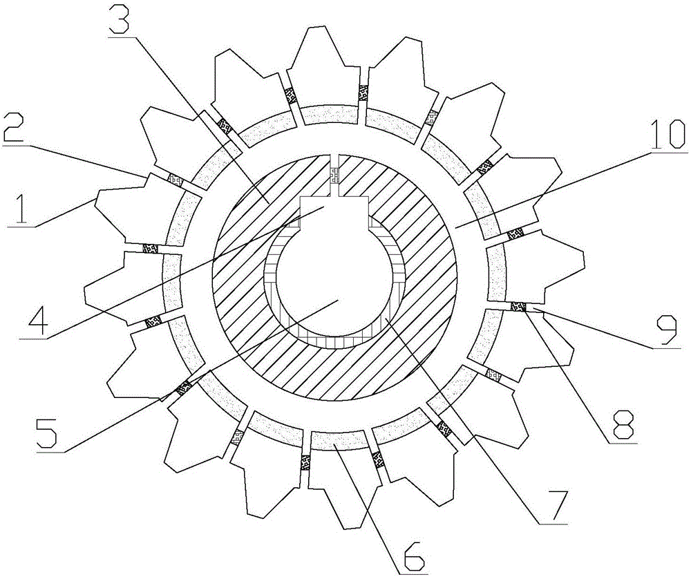
[0013] like figure 1 As shown, a noise-absorbing and shock-absorbing gear provided in this embodiment includes a gear body 3, teeth 1 are arranged on the outer contour of the gear body 3, and tooth grooves 2 are arranged between adjacent teeth 1, so that The central position of the gear body 3 is provided with a shaft hole 5, and a keyway 4 is provided on the inner wall of the shaft hole 5 and along the radial direction of the gear body 3. The surface of the gear body 3 is covered with a nickel-plated layer, which can reduce the use of the gear for a long time. Rust occurs during the ...


PUM


Abstract

The invention discloses a noise elimination vibration reduction gear which comprises a gear body, and further comprises an oil storage cavity, an elastic pressing piece and a foamed aluminium noise elimination layer, wherein teeth are arranged on the outer contour of the gear body; tooth grooves are formed between the adjacent teeth; a shaft hole is formed in the central position of the gear body; a keyway is formed in the inner wall of the shaft hole in the radial direction of the gear body; the oil storage cavity is formed inside the gear body; oil ducts are formed in the inner cavity wall of the oil storage cavity; the oil ducts are distributed on all the tooth grooves, and communicate with the upper surfaces of the tooth grooves; oil suction devices are arranged in the middle parts of the oil ducts; the elastic pressing piece is mounted around the inner wall of the shaft hole; and the foamed aluminium noise elimination layer is arranged on the inner wall of the oil storage cavity. According to the noise elimination vibration reduction gear, through the arranged elastic pressing piece, the oil ducts and the foamed aluminium noise elimination layer, when the gear runs, the elastic pressing piece reduces the friction of the shaft hole and a bearing, the oil ducts prevent the teeth from having dry friction, and the foamed aluminium noise elimination layer has a sound insulation effect.

Description

technical field [0001] The invention relates to the field of gears, in particular to a noise-absorbing and shock-absorbing gear. Background technique [0002] Since the second industrial revolution, the application of machinery has nearly occupied the entire manufacturing industry. Gears are an important part of the operation between various parts of machinery, but the noise generated by the gears during operation is relatively large. In the gear system, according to The mechanism is different, and the noise can be divided into two types: acceleration noise and self-sounding noise. On the one hand, when the gear teeth are meshing, the gear will generate a large acceleration due to the impact and cause the surrounding medium to be disturbed. The sound radiation generated is called the acceleration noise of the gear. On the other hand, under the action of the dynamic meshing force of the gear, the components of the system will vibrate. At the same time, because the shaft hole...

Claims


Application Information

Patent Timeline
Patent Type & Authority Applications(China)
IPC IPC(8): F16H55/17F16H57/04
CPCF16H55/17F16H57/043
Inventor 蒙泽喜
Owner 蒙泽喜
Why Eureka
Try Eureka