Cuttable and wearable stress sensor and preparation method thereof
A strain sensor and strain sensing technology, applied in the field of sensors, can solve problems such as not being able to meet wearable conditions, and achieve rapid large-area preparation, easy operation, and good product performance
- Summary
- Abstract
- Description
- Claims
- Application Information
AI Technical Summary
Problems solved by technology
Method used
Image
Examples
Embodiment 1
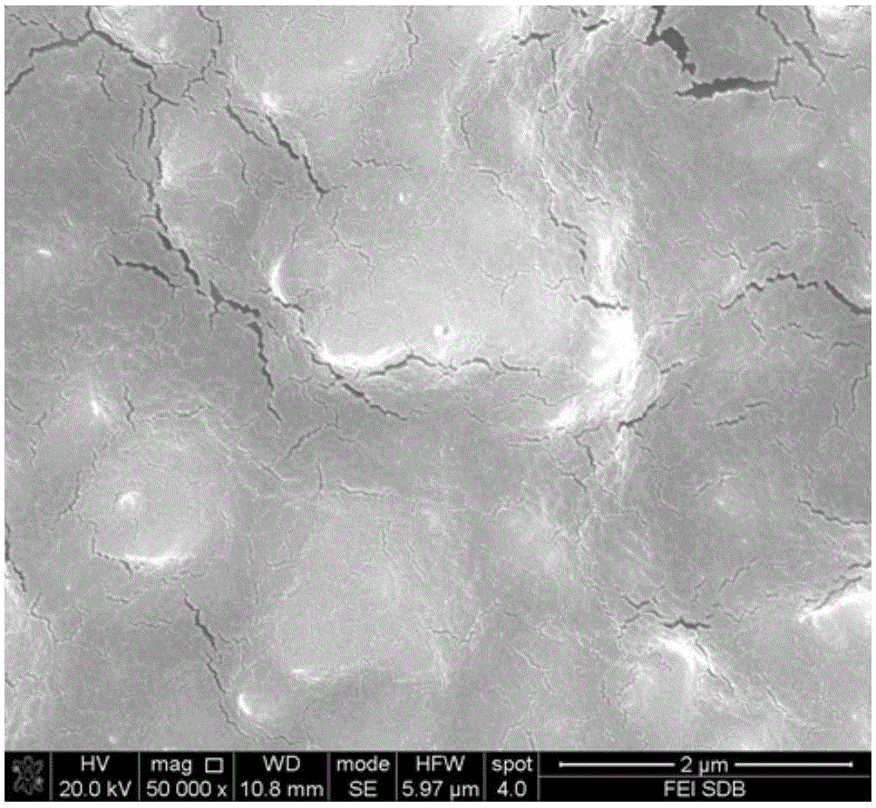
[0027] Step 1: Sputter a 50-nanometer thick gold nanofilm by DC sputtering on the surface of a rectangular sandpaper with a width of 4.0 centimeters and a mesh number of 10,000. The microscopic appearance of the formed gold nanofilm is as follows: figure 1 shown.
[0028] Step 2: Use scissors to cut into a cuttable wearable strain sensor with a length of 5.0 cm and a width of 3.0 cm.
[0029] Step 3: Use silver glue to lead out the wires from both ends of the sandpaper obtained in step 2 along the length direction to obtain a wearable strain sensor that can be cut. The schematic diagram of its structure is as follows figure 2 shown.
[0030] The obtained wearable shearable strain sensor with a length of 5.0 cm and a width of 3.0 cm is fixed on the index finger with double-sided tape, and can be used for finger bending detection, which can meet the 0-10 Hz finger bending monitoring.
Embodiment 2
[0032] Step 1: Sputter a 30 nanometer thick gold nano film by direct current sputtering on the surface of a rectangular sandpaper with a width of 3.0 cm and a width of 1.0 cm and a mesh number of 1500.
[0033] Step 2: Use scissors to cut into a cuttable wearable strain sensor with a length of 3.0 cm and a width of 0.5 cm.
[0034] Step 3: Use silver glue to draw wires from both ends of the sandpaper obtained in step 2 along the length direction to obtain a wearable strain sensor that can be cut.
[0035] The obtained cutable wearable strain sensor with a length of 3.0 cm and a width of 0.5 cm is fixed at the crack of the door with double-sided tape, and can be used to detect the opening and closing angle of the door. The detected opening and closing angle is -179 to Between 179 degrees.
Embodiment 3
[0037] Step 1: Sputter a 45 nm thick gold nano film by magnetron sputtering on the surface of a rectangular sandpaper with a width of 2.0 cm and a width of 0.5 cm and a mesh number of 2000.
[0038] Step 2: Use scissors to cut into a cuttable wearable strain sensor with a length of 2.0 cm and a width of 0.25 cm.
[0039] Step 3: Use silver glue to draw wires from both ends of the sandpaper obtained in step 2 along the length direction to obtain a wearable strain sensor that can be cut.
[0040] The obtained cutable wearable strain sensor with a length of 2.0 cm and a width of 0.25 cm is fixed on the arm skin with double-sided adhesive, and can be used to detect arm muscle activity, which can meet the 0-20 Hz muscle movement monitoring.
PUM
| Property | Measurement | Unit |
|---|---|---|
| Thickness | aaaaa | aaaaa |
| Length | aaaaa | aaaaa |
Abstract
Description
Claims
Application Information
 - R&D Engineer
- R&D Manager
- IP Professional
- Industry Leading Data Capabilities
- Powerful AI technology
- Patent DNA Extraction
Browse by: Latest US Patents, China's latest patents, Technical Efficacy Thesaurus, Application Domain, Technology Topic, Popular Technical Reports.
© 2024 PatSnap. All rights reserved.Legal|Privacy policy|Modern Slavery Act Transparency Statement|Sitemap|About US| Contact US: help@patsnap.com


