Surface Measurement Device Using Laser Rotation Scanning

A technology of rotating scanning and measuring devices, which is applied in the field of laser scanning systems, can solve problems such as high stability and complex structure, and achieve the effects of convenient control, simple control process and easy realization

Inactive Publication Date: 2018-06-05
TONGJI UNIV
View PDF12 Cites 1 Cited by
  • Summary
  • Abstract
  • Description
  • Claims
  • Application Information

AI Technical Summary

Problems solved by technology

However, the structure of the device is complex, the base and bracket of the device are processed with high precision, and high stability is required

Method used


Image

  • Surface Measurement Device Using Laser Rotation Scanning
  • Surface Measurement Device Using Laser Rotation Scanning
  • Surface Measurement Device Using Laser Rotation Scanning

Examples


Embodiment Construction

[0026] The following is a further detailed description of the composition of the laser-based rotary scanning surface measurement device and the surface measurement process of the present invention through various drawings, but the patent protection scope of the present invention is not limited thereto.

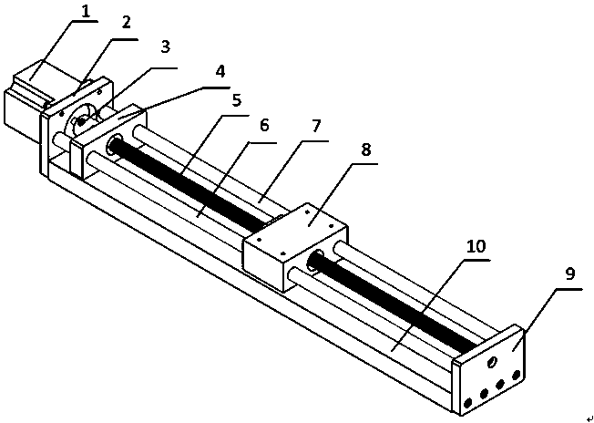
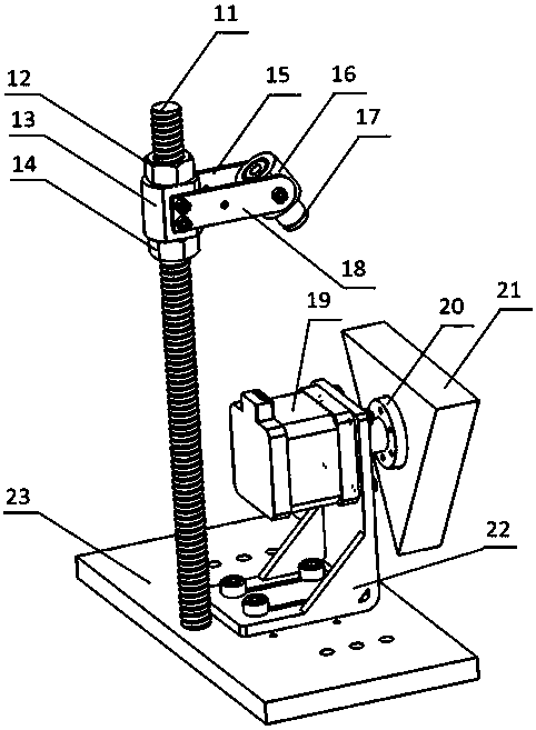
[0027] figure 1 Shown is a general schematic diagram of a surface measurement device based on laser rotation scanning, including three parts, which are respectively a one-dimensional sliding table system 32 (such as figure 2 shown), binocular vision measurement system 33 (such as Figure 5 shown), laser rotation scanning system 34 (such as image 3 shown) and the measured surface 35.

[0028] The one-dimensional slide system (such as figure 2 As shown) consists of the first rotary stepper motor 1, the motor support base 2, the coupling 3, the front support block 4, the ball screw 5, the first optical axis 6, the second optical axis 7, the linear slide table 8, the rear Th...


PUM


Abstract

The invention relates to a surface type measuring device adopting laser rotary scanning.The surface type measuring device is composed of a one-dimensional sliding table system, a laser rotary scanning system and a binocular vision measuring system.The one-dimensional sliding table system is composed of a first rotary stepping motor, a motor supporting seat, a coupler, a front supporting block, a ball screw, unthreaded shafts, a linear sliding table, a rear supporting seat and a base.The laser rotary scanning system is composed of a screw, a screw sleeve, connecting rods, a laser device sleeve, a laser device, a second rotary stepping motor, a polyhedron rotary mirror and a motor support.The binocular vision measuring system is composed of a bottom plate, cameras, supporting rods and set screws.According to the surface type measuring device, the second rotary stepping motor is used for driving the polyhedron rotary mirror to rotate, a laser emitted by the laser device irradiates a reflecting mirror of the polyhedron rotary mirror, and the laser point is reflected by the reflecting mirror and irradiates on a measured surface.The two cameras shoot the laser point irradiating the measured surface at the same time, a computer controls the shooting process of the two cameras and achieves real-time collecting and analyzing of shot data, and thus it is achieved that the computer controls output of three-dimensional coordinate points in binocular vision measuring.

Description

technical field [0001] The invention relates to a laser scanning system, in particular to a high-precision surface measurement device integrated with a polyhedron rotating mirror and a binocular vision measurement system. Background technique [0002] The prior technology (Minjiang University, Patent No.: 201510357389) mentions a binocular vision measurement method, which can take pictures of the measured points through two cameras, extract feature points from the photos taken, and use binocular stereo vision The three-dimensional coordinates of the feature points can be obtained by the related formulas of the measurement, and the accuracy can reach the micron level at the highest. Since the camera is installed on the laser rotating scanning device, the camera will shake during the shooting process, which will affect the accuracy of the obtained three-dimensional coordinates. Therefore, in the binocular vision measurement system, higher requirements are put forward for the ...

Claims


Application Information

Patent Timeline
Patent Type & Authority Patents(China)
IPC IPC(8): G01B11/16
CPCG01B11/16
Inventor 李安虎左其友
Owner TONGJI UNIV
Why Eureka
Try Eureka