
A multi-angle and multi-directional optical test platform

A technology of optical testing and testing platform, which is applied in the field of optical testing, can solve problems such as poor adjustability, and achieve the effect of solving poor adjustability

Active Publication Date: 2017-12-26
苏州德凡检测科技有限公司
View PDF8 Cites 2 Cited by
  • Summary
  • Abstract
  • Description
  • Claims
  • Application Information

AI Technical Summary

Problems solved by technology

[0005] The present invention overcomes the problems existing in the prior art, and proposes a multi-angle and multi-direction optical test platform, which can precisely adjust the spatial position and posture of the light source test piece at multiple angles, and solves the problem of the prior art's adjustable Defects such as sex difference

Method used


Image

  • A multi-angle and multi-directional optical test platform
  • A multi-angle and multi-directional optical test platform
  • A multi-angle and multi-directional optical test platform

Examples


Embodiment 1

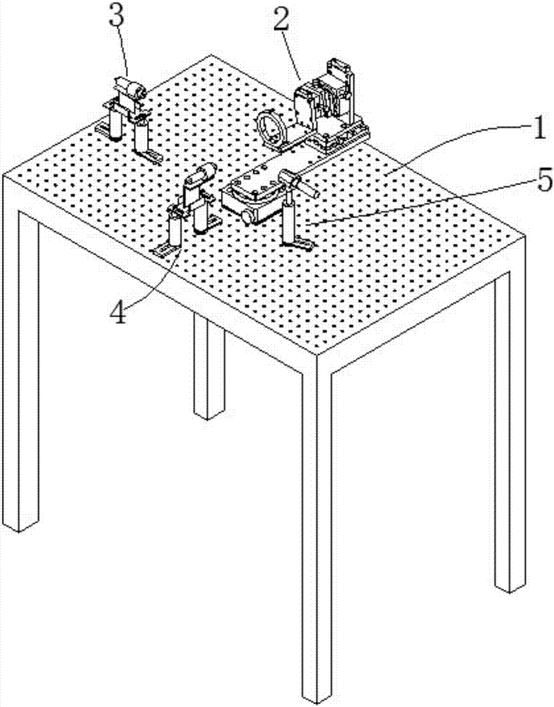
[0022] The present invention provides a multi-angle and multi-direction optical test platform, including a test platform 1, on which a full-angle rotating table 2, a laser transmitter fixture 3, a laser transmitter fixture 2 4, and an optical fiber probe fixture 5 are provided. ; Among them: the full-angle rotary table 2 is symmetrically arranged with the laser transmitter fixture 2 4, and the laser transmitter fixture 1 3 is symmetrically arranged with the fiber optic probe fixture 5.

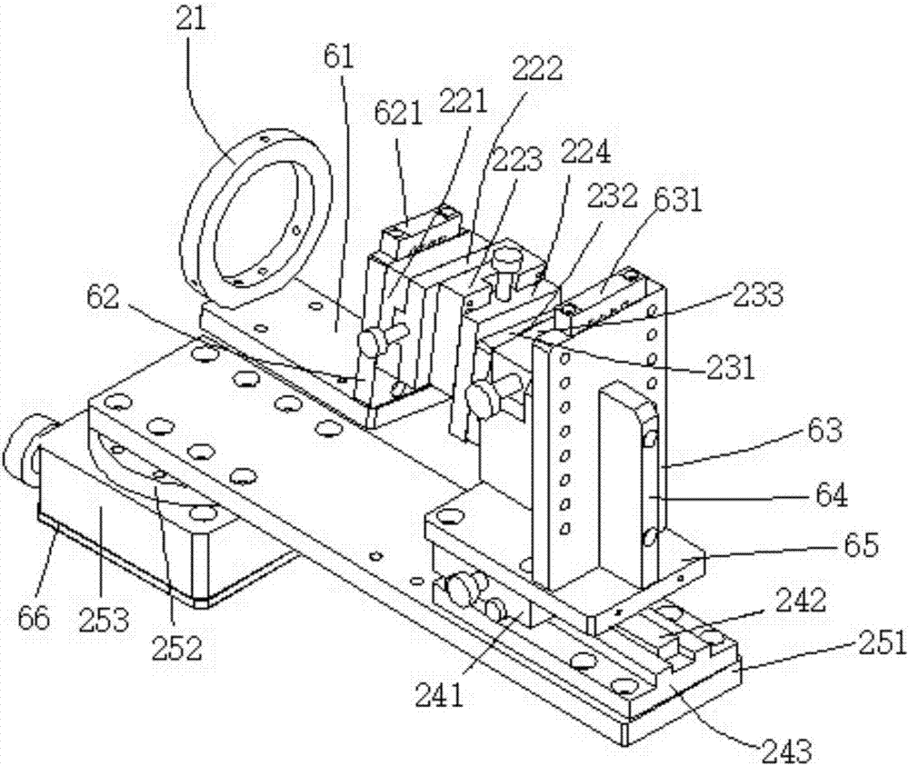
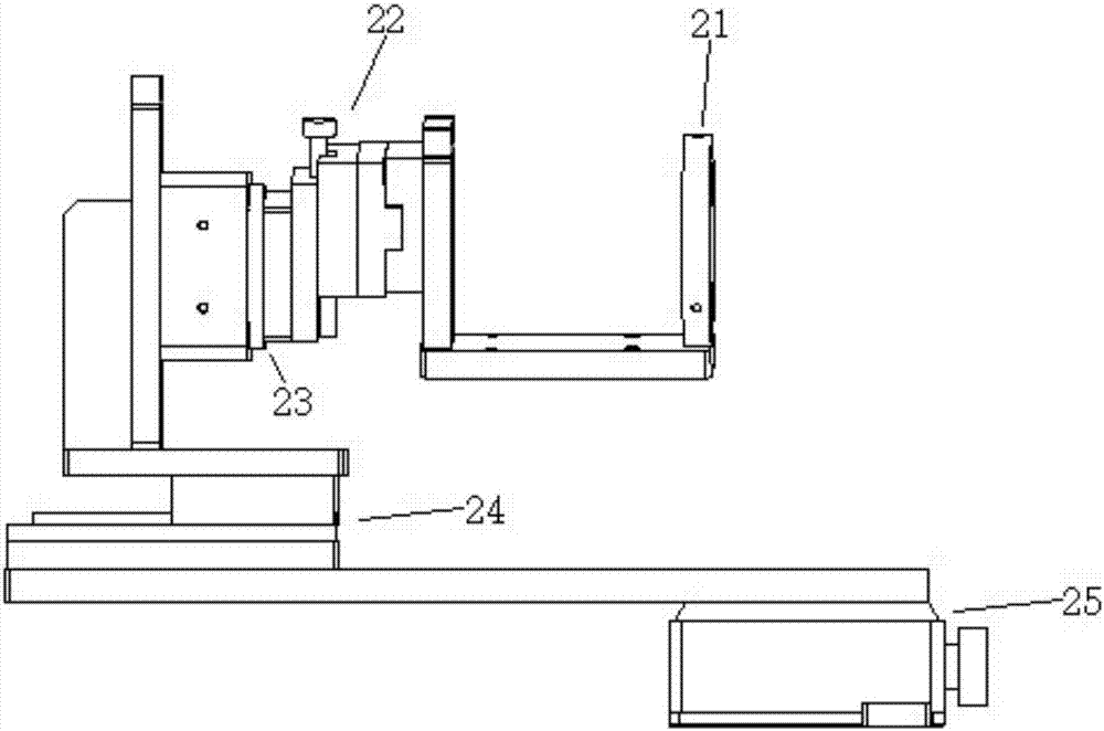
[0023] The full-angle rotating table 2 includes a three-point clamping adjustment frame 21, and the three-point clamping adjustment frame 21 is connected to the manual combined translation platform 22 through the lamp head connection base plate 1 61 and the lamp base connection base plate 2 62, and the manual combination translation platform 22 Including upper part one 221, chassis one 222, upper part two 223, and chassis two 224 connected in sequence, the manual combined translation platform 2...

Embodiment 2

[0028]The present invention provides a multi-angle and multi-direction optical test platform, including a test platform 1, on which a full-angle rotating platform 2, a laser transmitter fixture 3, a laser transmitter fixture 2 4, and an optical fiber probe fixture 5 are provided. ; Among them: the full-angle rotary table 2 is symmetrically arranged with the laser transmitter fixture 2 4, and the laser transmitter fixture 1 3 is symmetrically arranged with the fiber optic probe fixture 5.

[0029] The full-angle rotating table 2 includes a three-point clamping adjustment frame 21, and the three-point clamping adjustment frame 21 is connected to the manual combined translation platform 22 through the lamp head connection base plate 1 61 and the lamp base connection base plate 2 62, and the manual combination translation platform 22 Including upper part one 221, chassis one 222, upper part two 223, and chassis two 224 connected in sequence, the manual combined translation platform...


PUM


Abstract

The invention discloses a multi-angle multi-directional optical testing platform which comprises a testing platform body.The testing platform body is provided with an all-angle rotating platform, a first laser transmitter fixture, a second laser transmitter fixture and an optical fiber probe fixture, wherein the all-angle rotating platform and the second laser transmitter fixture are symmetrically installed, and the first laser transmitter fixture and the optical fiber probe fixture are symmetrically installed.The multi-angle multi-directional optical testing platform has the advantages of being capable of being conveniently placed in different environments and used for multi-angle multi-directional testing on light sources and meeting testing on parameters such as luminous flux, ultraviolet radiation and colors of the light sources.

Description

technical field [0001] The invention relates to the technical field of optical testing, in particular to a multi-angle and multi-directional optical testing platform. Background technique [0002] The luminous flux, ultraviolet radiation, and color of the light source are all important parameters in the application, and are important indicators for evaluating the light source. At present, the measurement of the light source adopts the optical detection platform. The optical detection platform is the carrying device for installing the optical detection host and the test piece. The precise focus adjustment of the position of the specimen during the detection process is realized through the drive system, traditional system, sensor system and other auxiliary devices installed on it, so as to complete the entire optical detection operation. Chinese patent application document CN202351022U discloses an optical test platform for a seeker marker, including a fixed end and a movable...

Claims


Application Information

Patent Timeline
Patent Type & Authority Patents(China)
IPC IPC(8): G01M11/04
CPCG01M11/04
Inventor 张帆
Owner 苏州德凡检测科技有限公司
Learn More