
IGBT power module unit load testing method

A power module and detection method technology, applied in the field of converters, can solve the problem that the current Hall of the power module cannot be fully verified IGBT power module unit, etc., and achieve the effects of low implementation cost, simple implementation, and simple control mode

Active Publication Date: 2016-07-27
GUANGDONG MINGYANG LONGYUAN POWER ELECTRONICS
View PDF4 Cites 2 Cited by
  • Summary
  • Abstract
  • Description
  • Claims
  • Application Information

AI Technical Summary

Problems solved by technology

[0005] In order to solve the above-mentioned technical problems, the object of the present invention is to provide a method for on-load detection of IGBT power module units that uses a semi-closed-loop control strategy to solve the problem that the power module current Hall cannot be fully verified.

Method used


Image

  • IGBT power module unit load testing method
  • IGBT power module unit load testing method

Examples


Embodiment Construction

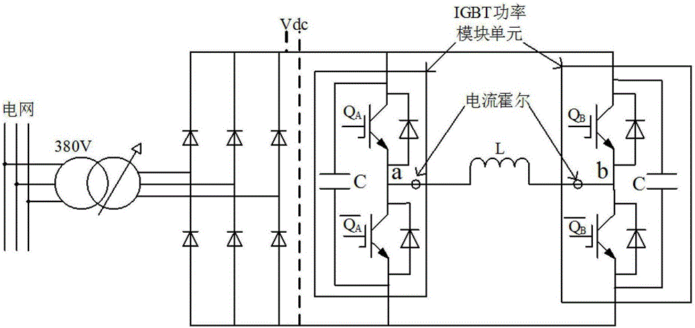
[0013] The circuit topology of the present invention is still based on the traditional IGBT power module unit, and the point of improvement lies in the software control strategy. Therefore, when the meaning of the present invention is explained below, it still has the same figure 1 topology combined.

[0014] (A) The test index of the power module unit is basically the same as that of the complete converter.

[0015] IGBT DC voltage Vdc=1100V, load reactance L=250uH, IGBT rated current IIGBT=1000A. Using SPWM modulation.

[0016] A phase module modulating wave is ;

[0017] Phase B modulation wave is , where m is the modulation ratio, =15°.

[0018] That is, the difference between A and B two-phase modulation waves is 15°, so the reactance load voltage is:

[0019]

[0020] Reactive load power frequency equivalent resistance:

[0021] Reactive load voltage drop: .

[0022] Therefore, according to the known parameters, the modulation ratio can be obtained ,...


PUM


Abstract

The invention discloses an IGBT power module unit load testing method. The method comprises the following steps that: (A) testing indexes of power module units are set to be identical with those of a current transformer whole machine; (B) a control system adopts a current Hall detection power module to detect the currents of the power module units; and (C) the current different between the two power module units is calculated, and when the current difference is larger than a set threshold, the power-off open circuit is used to trigger the protection over the IGBT power module units. The method has the advantages that: (1) the method is applicable to load aging tests of IGBT power modules of a wind power current transformer and a photovoltaic inverter; (2) the control mode is easy to realize, and the implementation cost is low; (3) current Hall verification is included, and the verification of the whole IGBT power module unit is more sufficient; and (4) the testing indexes of the IGBT power module units are identical with those of the current transformer whole machine, and the simulation of the real onsite condition of the IGBT is facilitated.

Description

technical field [0001] The invention relates to a converter, in particular to a load detection method for an IGBT power module unit. Background technique [0002] The IGBT power module unit is the core component of the converter. Whether its verification is sufficient or not and its performance is good or bad largely determines the reliability of the whole machine. Therefore, in order to reduce the failure rate of the power module of the whole machine, converter manufacturers generally use IGBT Power unit loading test platform. Before the power module is assembled into the complete converter, the on-load test of the power module is carried out to realize the rated current output aging test of the module and complete the verification of the components of the IGBT power module unit. [0003] like figure 1 As shown, the traditional IGBT power module unit loading test platform uses two half-bridge IGBT modules to form an H-bridge. The positive busbars of the two modules are con...

Claims


Application Information

Patent Timeline
Patent Type & Authority Applications(China)
IPC IPC(8): G01R31/00
CPCG01R31/00
Inventor 于虹李文清张佳丽王瑜谭丹李志华沈湘洪黎林周立专
Owner GUANGDONG MINGYANG LONGYUAN POWER ELECTRONICS
Learn More