Dust removal pipeline dust gas flow adjustment system

A flow adjustment and flow regulation technology, applied in the direction of flow control using electrical devices, etc., can solve the problems of multiple pipeline branches in the system, pollution of the production environment, labor and time consumption, etc., to achieve convenient installation and use, protection of production environment, and reliable operation. Effect

Inactive Publication Date: 2016-07-27
ACRE COKING & REFRACTORY ENG CONSULTING CORP DALIAN MCC
View PDF12 Cites 2 Cited by
  • Summary
  • Abstract
  • Description
  • Claims
  • Application Information

AI Technical Summary

Problems solved by technology

The specific manifestation is that some dust pollution sources cannot be effectively controlled. Some pipelines are quickly ground and damaged due to the high actual dust flow velocity, and some pipelines are caused by dust settlement and accumulation in the pipeline due to the low actual dust flow velocity, resulting in pipeline blockage. The dust removal system loses effective control of the dust pollution source, and the dust removal effect is poor, which will still cause pollution to the production environment
[0004] Since the dust removal system usually needs to control multiple dust pollution sources at the same time, the system pipeline has many branches and complex structure, and the adjustment of the dust gas flow in the pipeline interferes with each other and affects each other when the system is running, and the adjustment means are limited to each branch. The adjustment of the manual or electric control valve installed on the pipeline can only refer to the control effect of each dust pollution source. Therefore, the adjustment of the dust flow of the dust removal system needs repeated trials and observations, which consumes a lot of manpower and time.
Even so, it is difficult to get the expected good effect

Method used


Image

  • Dust removal pipeline dust gas flow adjustment system
  • Dust removal pipeline dust gas flow adjustment system
  • Dust removal pipeline dust gas flow adjustment system

Examples


Embodiment Construction

[0029] The specific embodiment of the present invention will be further described below in conjunction with accompanying drawing:

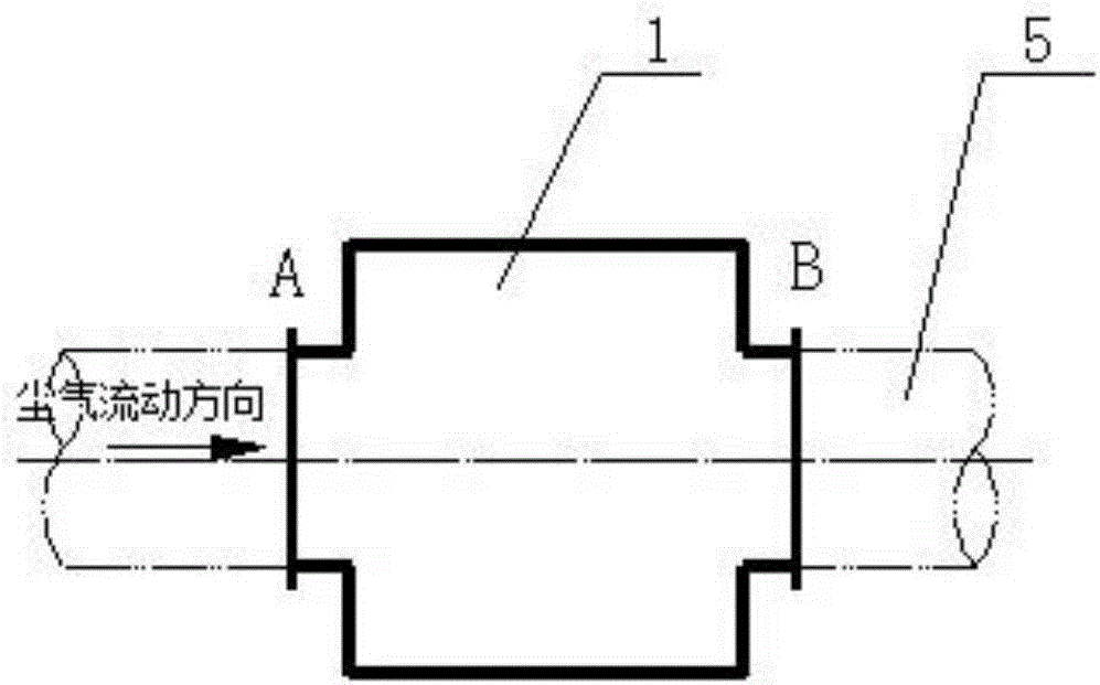
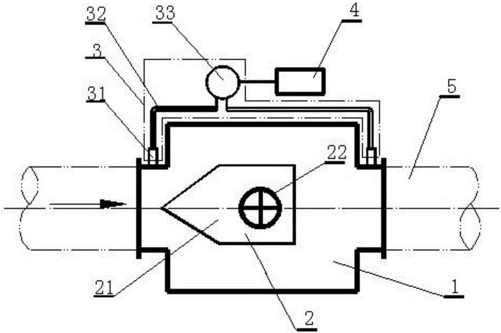
[0030] Such as figure 1 and figure 2 As shown, the dust gas flow adjustment system of the dust removal pipeline according to the present invention includes a cylinder body 1, a dust gas flow adjustment unit 2, a pressure difference detection unit 3 and a control unit 4, and the cylinder body 1 is installed on the dust removal pipeline 5 The cylinder body 1 is equipped with a dust gas flow regulating unit 2, and the cylinder body 1 is equipped with a differential pressure detection unit 3, and the output end of the differential pressure detection unit 3 is connected to the control terminal of the dust gas flow regulating unit 2 through the control unit 4.

[0031] Both ends of the cylinder body 1 have a diameter matched with the dust removal pipeline 5, and the dust gas flow adjustment unit 2 is a throttling body. Through manual or electric adjus...


PUM


Abstract

The invention relates to a dust removal pipeline dust gas flow adjustment system.The system comprises a barrel, a dust gas flow adjustment unit, a differential pressure detection unit and a control unit, the barrel is installed on a dust removal pipeline, the barrel is internally provided with the dust gas adjustment unit, the differential pressure detection unit is arranged outside the barrel, and the output end of the differential pressure detection unit is connected with the control end of the dust gas flow adjustment unit through the control unit.According to the dust removal pipeline dust gas flow adjustment system, the dust gas flow in a dust removal pipeline can be online monitored in real time, rapid and effective adjustment is conducted according to needs, the dust removal system can reach an ideal state of design, it is guaranteed that the dust removal system operates safely, stably and reliably, and the production environment is protected; meanwhile, by means of measurement and adjustment on the dust gas flow in the dust removal pipelines at all dust sources, the optimal control flow of the dust sources is obtained, valuable measured data is accumulated for the design and production, and optimization of the design and production is achieved gradually.

Description

technical field [0001] The invention relates to the technical field of gas flow adjustment, in particular to a dust gas flow adjustment system for a dust removal pipeline. Background technique [0002] The dust removal system is an effective means for controlling and purifying various dust pollution sources in the industrial production process. The design of the dust removal system should be based on a full understanding of the emission intensity and dust characteristics of each dust pollution source, and based on theoretical calculations and practical experience, to determine the best control dust gas volume that can effectively control each dust pollution source, and then combine the system The spatial location of the equipment and each dust-containing pollution source finally determines the optimal pipeline, equipment layout and type selection. [0003] In the adjustment and production operation after the actual start of construction, the dust removal system often deviat...

Claims


Application Information

Patent Timeline
Patent Type & Authority Applications(China)
IPC IPC(8): G05D7/06
CPCG05D7/06
Inventor 王满
Owner ACRE COKING & REFRACTORY ENG CONSULTING CORP DALIAN MCC
Why Eureka
Try Eureka