ETC system integrated with infrared camera function, and vehicle identification and location method

An infrared camera and vehicle identification technology, applied in the field of ETC, can solve problems such as vehicle positioning errors, car-following interference, transaction confusion, etc., and achieve the effect of improving transaction success rate, improving reliability and safety, and reducing radio frequency interference

Inactive Publication Date: 2016-07-27
AEROSPACE INFORMATION
View PDF9 Cites 14 Cited by
  • Summary
  • Abstract
  • Description
  • Claims
  • Application Information

AI Technical Summary

Problems solved by technology

[0003] In practical applications, when there are multiple vehicle-mounted OBUs within the coverage of a certain RSU, the RSU may not be able to distinguish these vehicle-mounted OBUs, resulting in car-following interference, wrong vehicle positioning, wrong payment, etc., and in the existing ETC system, RSUs and OBUs located in adjacent lanes may also generate adjacent lane interference, which can cause transaction confusion

Method used


Image

  • ETC system integrated with infrared camera function, and vehicle identification and location method
  • ETC system integrated with infrared camera function, and vehicle identification and location method

Examples


Embodiment Construction

[0023] Specific embodiments of the present invention will be described in detail below in conjunction with the accompanying drawings. It should be understood that the specific embodiments described here are only used to illustrate and explain the present invention, and are not intended to limit the present invention.

[0024] In the present invention, unless stated to the contrary, the used orientation words such as "radial" generally refer to the direction in which vehicles on the ETC lane travel.

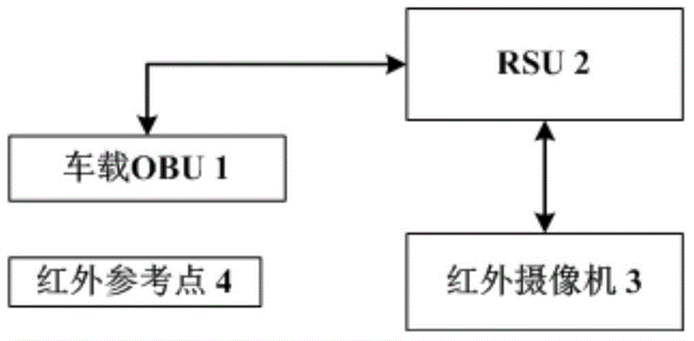
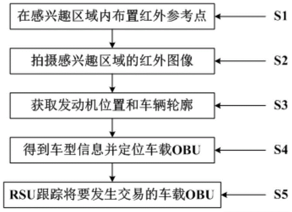
[0025] The invention discloses an ETC system with integrated infrared camera function. The ETC system includes: a vehicle-mounted OBU and a roadside unit, and the vehicle-mounted OBU and the roadside unit communicate through wireless signals to complete data transmission and payment; an infrared camera, installed above the ETC lane, is used to capture an infrared image of the area of ​​interest and transmit the corresponding information to the roadside unit, and the infrared image...


PUM


Abstract

The invention discloses an ETC system integrated with the infrared camera function, and a vehicle identification and location method. The ETC system comprises a vehicle-mounted OBU and a road-side unit. The vehicle-mounted OBU and the road-side unit are in communication through wireless signals, so that the data transfer and the payment are realized. An infrared camera is installed above the lane of the ETC and is used for capturing an infrared image of an interested region and transmitting the corresponding information to the road-side unit. The infrared image is used for acquiring the engine position of a vehicle and the profile of the vehicle. An infrared reference point is located within the interested region and is adopted as a reference during the acquiring process of the engine position and the profile of the vehicle. Based on the ETC system, by utilizing the infrared image, the type information of the vehicle can be obtained and the vehicle-mounted OBU is facilitated to be positioned. Therefore, the transaction success rate and the reliability of the ETC system are improved.

Description

technical field [0001] The present invention relates to the field of ETC (namely ElectronicTollCollection), in particular to an ETC system integrating infrared camera identification function and a vehicle identification and positioning method used in the ETC system. Background technique [0002] The ETC system is an automatic electronic toll collection system that is mainly researched and promoted in the world at present, and it is suitable for vehicle toll collection solutions in highways and bridges and tunnels with heavy traffic. The standard accessories of the ETC system include on-board OBU (On-BoardUnit, also known as on-board electronic label or on-board electronic unit) and roadside unit (RoadSideUnit). The vehicle-mounted OBU is installed on the vehicle. When the vehicle passes the toll station on the ETC lane, the vehicle-mounted OBU communicates with the roadside unit (RSU, RoadSideUnit) through radio frequency wireless signals, and the toll payment can be complet...

Claims


Application Information

Patent Timeline
Patent Type & Authority Applications(China)
IPC IPC(8): G07B15/06
Inventor 邓海刘洋周悦
Owner AEROSPACE INFORMATION
Why Eureka
Try Eureka