Detector signal readout channel multiplexing method

A signal readout and signal multiplexing technology, which is applied in the field of nuclear detection technology and nuclear medical imaging, can solve the problems of reducing electronic channels and large dynamic range of output signals, so as to achieve compact detectors, reduce complexity, and improve integration Effect

Active Publication Date: 2016-08-03
RAYCAN TECH CO LTD SU ZHOU
View PDF5 Cites 9 Cited by
  • Summary
  • Abstract
  • Description
  • Claims
  • Application Information

AI Technical Summary

Problems solved by technology

[0005] In view of this, the purpose of the present invention is to provide a channel multiplexing method for detector signal readout, which can reduce the use

Method used


Image

  • Detector signal readout channel multiplexing method
  • Detector signal readout channel multiplexing method
  • Detector signal readout channel multiplexing method

Examples


Embodiment Construction

[0051] The invention discloses a channel multiplexing method for detector signal readout, which can effectively solve the problem that the dynamic range of the output signal after the multiplexing of the detector channels is too large.

[0052] like Figure 4 to Figure 5 As shown, the present invention discloses a channel multiplexing method for detector signal readout, which specifically includes steps:

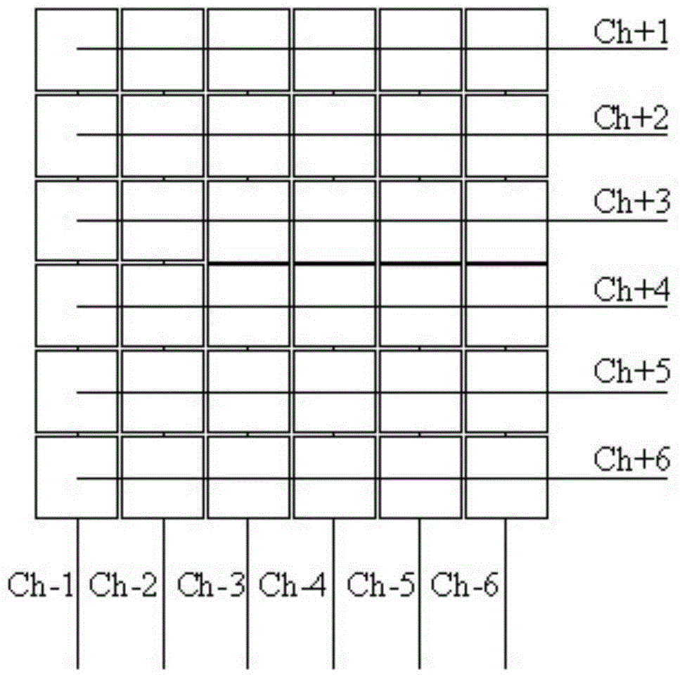
[0053] S1: Divide L detector signals into M groups, the number of detectors in each group is at least 2, and the maximum is N, where the number of detector signals in group a is P(a), The bth detector signal of the ath group is marked as Signal(a,b), M≥2, N≥2, 1≤a≤M, 1≤b≤N;

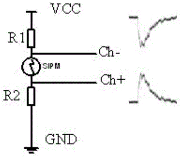
[0054] S2: Divide the output signals of the detectors in step S1 into row source signals and column source signals, wherein the row source signals of the detectors in group a are summed to form row signals, and finally M groups form M rows signal, add the column source signals of the bth detector in ...


PUM


Abstract

An array detector signal readout channel multiplexing method comprises the steps of dividing array detectors into M groups; each group includes at least two detectors; readout channels are converted into M rows and N columns to readout signals in a rank coding manner, namely the ath row signal and the bth column signal are correspondingly output when the detector at the ath row and the bth column outputs a signal; the signals read out from the row and the column are respectively accessed to different positions of two transmission lines; and determining the source row and column number of the signal according to time difference when the signal reaches two end points of each transmission line, and marking the source detector where the signal is generated according to two groups of time differences of the row and column signals. Application of multiple electronics channels is prevented, and cost and engineering implementation difficulty of an electronics system are reduced; and due to the fact that application of a resistor weighting network is prevented during the channel multiplexing process, the amplitude of the signal cannot be largely changed due to different access points of the signal after multiplexing, and requirements on dynamic ranges of a rear-end readout circuit are reduced.

Description

technical field [0001] The invention relates to the fields of nuclear detection technology and nuclear medical imaging technology, in particular to a channel multiplexing method for detector signal readout. Background technique [0002] In a clinical positron emission tomography (Positron Emission Tomography, hereinafter referred to as PET) equipment, the number of detectors is as many as 30,000. Direct readout of the electrical signal produced by each detector requires 30,000 channels of electronic processing. The large number of electronic channels makes the entire PET electronic system expensive and difficult to implement. [0003] In response to the above situation, researchers focused on the research and development of channel multiplexing technology for detector signal readout. The current mainstream readout channel multiplexing method is to weight the output signal of the detector signal by row and column with a resistor network and then read it out. [0004] The u...

Claims


Application Information

Patent Timeline
IPC IPC(8): A61B6/03
CPCH04N25/75G01T1/164G01T1/2985
Inventor 奚道明刘祥刘苇曾晨谢庆国
Owner RAYCAN TECH CO LTD SU ZHOU
Why Eureka
Try Eureka