Multi-cavity concrete filled steel tube combination column supporting frame system installed in supported and inserted mode

A technology of concrete filled steel tube and supporting frame, which is applied in the direction of construction and building structure, can solve the problems of poor quality of welding seam, shorten the service life of frame, large welding residual stress, etc., so as to improve the service life, ensure the quality of welding seam, The effect of strong carrying capacity

Active Publication Date: 2016-08-03
XI'AN UNIVERSITY OF ARCHITECTURE AND TECHNOLOGY
View PDF9 Cites 0 Cited by
  • Summary
  • Abstract
  • Description
  • Claims
  • Application Information

AI Technical Summary

Problems solved by technology

Because when the side length is small, it is not only difficult to weld, but also hinders the concrete pouring in the pipe. In addition, the beam flange and the inner partition plate penetrate the weld seam on both sides of the same column wall, the quality of the weld seam is poor, and the steel produces large welding residual stress. The steel at the joints is prone to delamination or brittle failure, thereby reducing the service life of the frame
[0004] 2) Affect the appearance and use of buildings
And when applied to corner columns, the horizontal ring plate not only hinders the installation of wall panels, but also causes the reinforcement ring to protrude from the building facade, causing convex corners at the indoor and outdoor joints, which affects the look and feel, which needs to be solved by decoration or ceiling
[0005] 3) The mechanical properties of the joints in the frame and the simplicity and economy of construction cannot be both
In practical applications, some types of joints have better mechanical properties and the overall stiffness of the frame is also good, but the amount of materials is large and the construction is complicated

Method used


Image

  • Multi-cavity concrete filled steel tube combination column supporting frame system installed in supported and inserted mode
  • Multi-cavity concrete filled steel tube combination column supporting frame system installed in supported and inserted mode
  • Multi-cavity concrete filled steel tube combination column supporting frame system installed in supported and inserted mode

Examples


Embodiment Construction

[0029] The present invention is described in further detail below in conjunction with accompanying drawing:

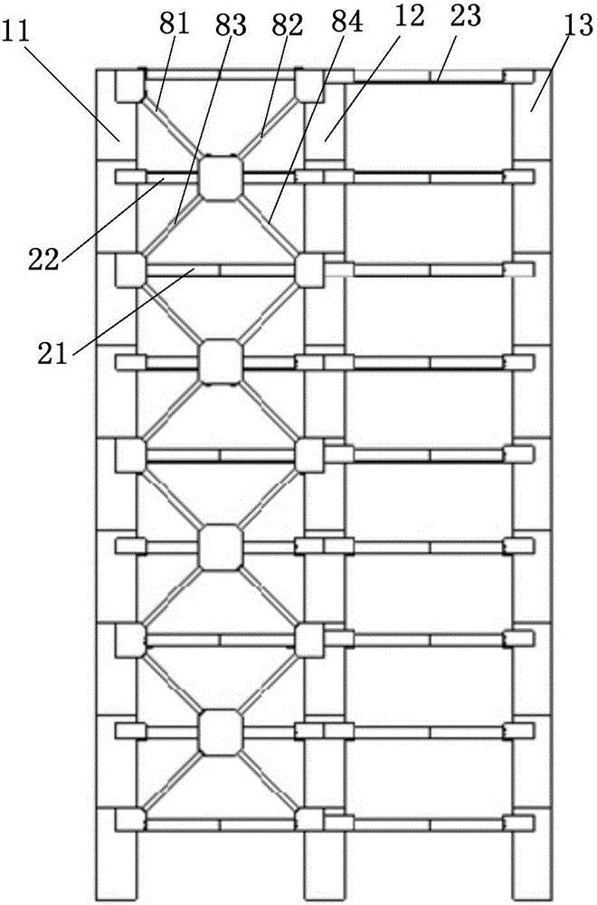
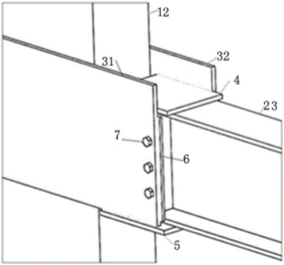
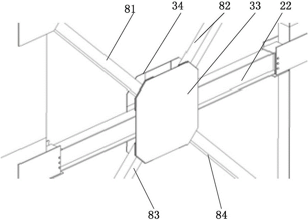
[0030] refer to figure 1 , figure 2 , image 3 and Figure 4 , the multi-cavity concrete-filled steel pipe composite column support frame system for support insertion installation according to the present invention includes a first multi-cavity steel pipe concrete composite column 11, a second multi-cavity steel pipe concrete composite column 12 and a third multi-cavity steel pipe concrete composite column distributed in sequence from left to right. Cavity concrete-filled steel pipe composite column 13; several first H-shaped steel beams 21 are arranged between the first multi-cavity steel-filled concrete composite column 11 and the second multi-cavity steel-filled concrete composite column 12, and each first H-shaped steel beam 21 runs from top to bottom The bottom is distributed in sequence, and a support system is provided between the two first H-shaped steel be...


PUM


Abstract

The invention discloses a multi-cavity concrete filled steel tube combination column supporting frame system installed in a supported and inserted mode. The system comprises a first multi-cavity concrete filled steel tube combination column, a second multi-cavity concrete filled steel tube combination column and a third concrete filled steel tube combination column which are sequentially distributed from left to right. A plurality of first H-shaped steel beams are arranged between the first multi-cavity concrete filled steel tube combination column and the second multi-cavity concrete filled steel tube combination column and sequentially distributed from top to bottom. A supporting system is arranged between two first H-shaped steel beams adjacent vertically and comprises a second H-shaped steel beam, first supporting square steel, second supporting square steel, third supporting square steel and fourth supporting square steel. The system is long in service life, good in observability and simple in structure, the rigidity of a frame is high, and construction is convenient.

Description

technical field [0001] The invention relates to a frame system, in particular to a multi-cavity steel pipe concrete composite column support frame system for support insertion and installation. Background technique [0002] At present, my country's "Technical Regulations for Rectangular Steel Tube Concrete Structures" (GECS159: 2004) provides a frame for steel tube beam-column joints, which mainly consists of joints in the form of inner diaphragm type and outer ring plate type. But so far, there are the following deficiencies in the connection between the steel pipe concrete composite column and the steel beam node in the prior art: [0003] 1) When the inner diaphragm and the flange of the beam in the inner diaphragm joint are in the same horizontal plane, the joint meets the requirements of rigid joints, but this kind of joint can only be used when the side of the pipe column is longer. Because when the side length is small, it is not only difficult to weld, but also hind...

Claims


Application Information

Patent Timeline
IPC IPC(8): E04B1/30E04B1/58
CPCE04B1/185E04B1/30
Inventor 刘斌郝际平樊春雷薛强孙晓岭陈永昌黄育琪王磊何梦楠尹伟康刘瀚超张峻铭赵子健
Owner XI'AN UNIVERSITY OF ARCHITECTURE AND TECHNOLOGY
Why Eureka
Try Eureka