Acoustic-electric imaging logging instrument

An imaging logging and imager technology, applied in the direction of wellbore/well components, earthwork drilling and production, etc., can solve the problem of not being on the same instrument, so as to save construction time and cost, reduce the risk of engineering accidents, and wide dynamic measurement range Effect

Inactive Publication Date: 2016-08-03
CHENGDU CHUANGYUAN OIL & GAS TECH DEV
View PDF5 Cites 5 Cited by
  • Summary
  • Abstract
  • Description
  • Claims
  • Application Information

AI Technical Summary

Problems solved by technology

[0003] The acoustoelectric imaging logging instrument of the present invention solves the problem in the prior art that the resistivity imager and the acoustic wave imager are not on the same instrument, so that one tool can go down the well at one time to obtain two kinds of measurements of resistivity imaging and acoustic wave imaging. Well plan, saving construction period and cost, reducing the risk of engineering accidents

Method used


Image

  • Acoustic-electric imaging logging instrument

Examples


Embodiment 1

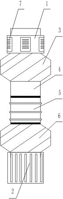
[0017] Such as figure 1 The acoustoelectric imaging logging instrument shown includes a resistivity imager 1 and an acoustic wave imager 2 for well logging. The resistivity imager 1 and the acoustic wave imager 2 are on the same instrument, and the resistivity imager The instrument 1 is located on the upper part of the acoustic wave imager 2, and an upper centralizer 3, an azimuth short joint 4, a universal joint 5, and a lower centralizer 6 are sequentially connected between the resistivity imager 1 and the acoustic wave imager 2; On the resistivity imager 1, there are six independently movable plates 7 pushed by springs evenly distributed in a ring; the resistivity imager 1 is a micro-resistivity scanning imaging logging instrument; the acoustic imager 2 is an acoustic wave scanning around the well. Imaging logging tools. In this embodiment, the acoustic imager 2 is arranged at the lower part of the instrument string to reduce the logging blind area (that is, the zero lengt...


PUM


Abstract

The invention discloses an acoustic-electric imaging logging instrument. The acoustic-electric imaging logging instrument comprises a resistivity imager for logging and a sound wave imager, wherein the resistivity imager and the sound wave imager are positioned on one instrument, the resistivity imager is positioned at the upper part of the sound wave imager, and an upper centralizer, a direction short joint, a universal joint and a lower centralizer are sequentially connected between the resistivity imager and the sound wave imager. The acoustic-electric imaging logging instrument has the advantages that the problem of the resistivity imager and the sound wave imager not in the same instrument in the prior art is solved, the two logging maps of resistivity imaging and sound wave imaging can be completed by one tool through one-time logging, the construction period is shortened, the cost is reduced, and the risk of engineering accidents is decreased.

Description

technical field [0001] The invention relates to the field of petroleum and natural gas exploration and development, in particular to an acoustic-electric imaging logging instrument. Background technique [0002] Imaging logging is a method of imaging physical parameters of the borehole wall and objects around the well based on the observation of the geophysical field in the borehole, including borehole wall imaging, wellside imaging and interwell imaging. Among them, borehole imaging is the most widely used logging method, which is mainly divided into two imaging methods: resistivity imaging and acoustic imaging. In the prior art, resistivity imaging and acoustic wave imaging instruments are two independent logging instruments, each of which has an independent azimuth sub, centralizer, upper and lower joints, and the like. Among them, the resistivity imaging logging tool has a wide dynamic measurement range, while the acoustic logging tool can perform 360° complete borehole...

Claims


Application Information

Patent Timeline
Patent Type & Authority Applications(China)
IPC IPC(8): E21B49/00
CPCE21B49/00
Inventor 金涛张鑫
Owner CHENGDU CHUANGYUAN OIL & GAS TECH DEV
Why Eureka
Try Eureka