Displacement pump and conveying method thereof
A technology of positive displacement pump and drive shaft, applied in the direction of pumps, pump components, rotary piston pumps, etc., can solve the problems of transmitting fluids from different sources that have not yet been seen, and achieve the effect of simple structure, stable flow and large selection range.
- Summary
- Abstract
- Description
- Claims
- Application Information
AI Technical Summary
Problems solved by technology
Method used
Image
Examples
Embodiment 1
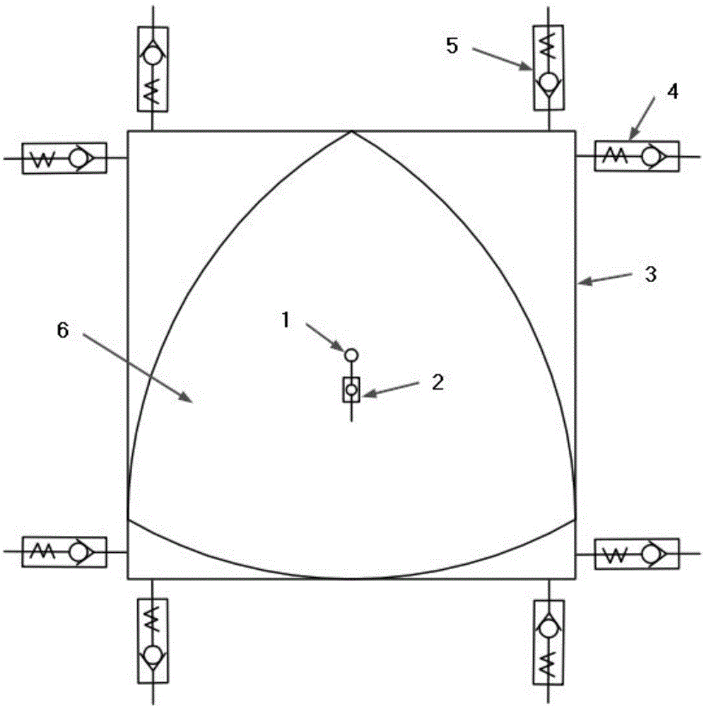
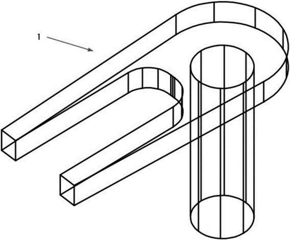
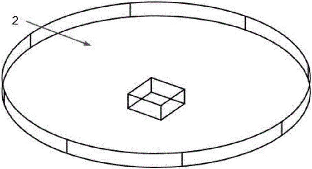
[0048] A positive displacement pump such as figure 1 , figure 2 , image 3 , Figure 4 and Figure 6As shown, it is a Leroy triangular rotor positive displacement pump, which includes a rotor 6 , a housing 9 , a transmission shaft 1 , a first one-way valve 4 , a second one-way valve 5 and a transmission connector 2 . The cross-section of the radial outer contour of the rotor 6 is in the shape of a Reroux triangle, and is provided with a groove for accommodating the transmission shaft 1 and the transmission connection part 2 . The cross-section of the radially inner contour of the housing 9 is square, and has a support line with the same width as the rotor of the Reroux triangle. The transmission shaft 1 is provided with a chute, the four corners of the housing 9 are respectively provided with the first one-way valve 4 and the second one-way valve 5, and the first one-way valve 4 and the second one-way valve The one-way valve 5 can be a plurality of one-way valves install...
Embodiment 2
[0052] Such as figure 1 , figure 2 , image 3 , Figure 5 , Figure 6 As shown, wherein, the rotor 6 is placed in the housing 9, and the end of the transmission shaft 1 with a chute is located in the housing, and the chute is connected with the protruding structure of the rotor 6, and the groove of the transmission shaft 1 rotor 6 Inside, the depth of the groove is enough to accommodate the protruding structure of the transmission shaft 1 and the rotor 6; the first one-way valve 4 and the second one-way valve 5 are arranged in pairs near the four corners of the housing 9, where the rotor 6 rotates In the area where the outer boundary of the trajectory does not coincide with the right-angled side of the housing 9, 8 check valves are installed in pairs and reversed, respectively located at 4 corners, and each pair of check valves is installed on the opposite side; the volume of the Leroy triangular rotor The pump is assembled and sealed, just connect the pipes to each one-w...
Embodiment 3
[0055] Such as figure 1 , figure 2 , image 3 , Figure 4 , Figure 6 As shown, a Leroux triangular rotor volumetric pump of the present invention includes a rotor 6 , a housing 9 , a transmission shaft 1 , a first check valve 4 and a second check valve 5 , and a transmission connector 2 . Wherein, the radial outer contour of the rotor 6 is in the shape of a Reloux triangle and has a groove for accommodating the transmission shaft 1 and the transmission connector 2, and the radial inner contour of the housing 9 is square and is equal to the width of the Reloux triangle rotor. The supporting line, the transmission shaft 1 has a chute, the first one-way valve 4 and the second one-way valve 5 are placed at the four corners of the housing and are composed of a plurality of one-way valves installed in pairs and reversed, One end of the transmission connector 2 is located in a matching groove at the radial center of the rotor 6 and the other end is connected to the chute of the...
PUM
 Abstract
Description
Claims
Application Information
 - R&D
- Intellectual Property
- Life Sciences
- Materials
- Tech Scout
- Unparalleled Data Quality
- Higher Quality Content
- 60% Fewer Hallucinations
Browse by: Latest US Patents, China's latest patents, Technical Efficacy Thesaurus, Application Domain, Technology Topic, Popular Technical Reports.
© 2025 PatSnap. All rights reserved.Legal|Privacy policy|Modern Slavery Act Transparency Statement|Sitemap|About US| Contact US: help@patsnap.com


