
Anti-cavitation cantilever centrifugal pump and manufacturing method thereof

A centrifugal pump and anti-cavitation technology, which is applied in the direction of pumps, pump components, non-variable pumps, etc., can solve the problems that the performance parameters of centrifugal pumps cannot meet the device requirements, the pump curve is prone to humps, and standard water pumps have cavitation. , to achieve superior cavitation resistance, easy control of dimensional tolerances, and stable product manufacturability

Inactive Publication Date: 2016-08-03
沈阳市工业泵厂(有限公司)
View PDF5 Cites 2 Cited by
  • Summary
  • Abstract
  • Description
  • Claims
  • Application Information

AI Technical Summary

Problems solved by technology

[0002] When the current centrifugal pumps manufactured according to general standards are applied to devices with low NPSH, due to the low NPSH of the device, cavitation occurs during use of the standard pump and cannot operate at the rated flow rate. The performance parameters of the centrifugal pump cannot meet the device requirements
[0003] In addition, when the flow rate of the device is small, the existing standard centrifugal pump needs to operate at a small flow rate, which does not meet the standard regulations and the principle of pump selection, resulting in unstable operation of the pump, large vibration, and the pump curve is prone to humps, so it cannot be achieved. Technical Requirements for Smooth Operation

Method used


Image

  • Anti-cavitation cantilever centrifugal pump and manufacturing method thereof
  • Anti-cavitation cantilever centrifugal pump and manufacturing method thereof
  • Anti-cavitation cantilever centrifugal pump and manufacturing method thereof

Examples


Embodiment Construction

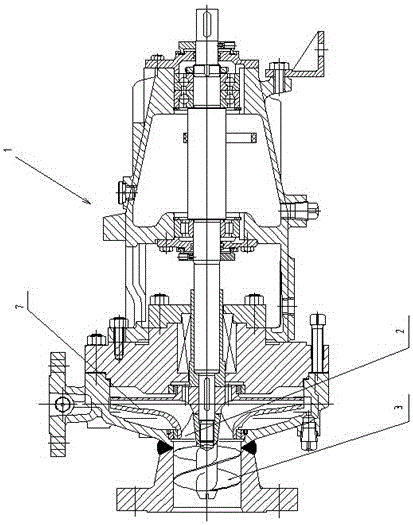
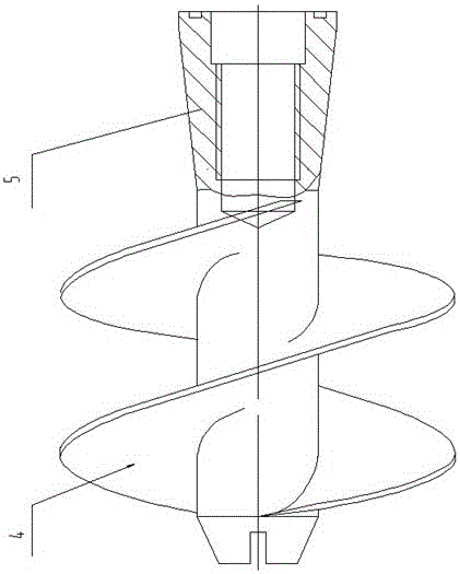
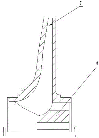
[0017] see Figure 1~3 In the single-stage cantilever pump 1, the impeller inlet 2 at the front of the impeller 7 is provided with an inducer 3, the inducer is a welded inducer, and the blade 4 of the inducer is made of steel sheet, and the thickness of the blade can be reduced to 2mm, can be reduced to thinner according to needs, the blade of the inducer is welded on the hub 5 of the inducer; the width of the impeller outlet 7 of the single-stage cantilever pump is smaller than the height of the impeller base 6 .

[0018] Its preparation method comprises the following steps:

[0019] 1) Prepare the components of the centrifugal pump (except the front cover of the impeller) and the inducer according to the standard. The hub of the inducer is turned from a bar, and the hub of the inducer is shuttle-shaped; the blades of the inducer are sheet metal The piece is processed by a sheet metal fitter, and its shape is a radian on the Z axis in the space coordinate system, and the pro...


PUM

PropertyMeasurementUnit
Thicknessaaaaaaaaaa

Abstract

The invention provides an anti-cavitation cantilever centrifugal pump and a manufacturing method thereof, and aims at solving the following problem that when an existing standard centrifugal pump operates at a lower-capacity point and a net positive suction head of a device is extremely low, cavitation occurs in the pump to cause unstable running, serious vibration, and easy formation of pump curve humps, thus leading to a failure in meeting the technical requirements of stable running. The anti-cavitation cantilever centrifugal pump is technically characterized in that an inducer, which is a welded inducer, is arranged at an impeller inlet of a single-stage cantilever pump; an impeller of the inducer is formed by sheet steel with a thickness of 2mm, and welded on a hub of the inducer; and an impeller outlet is narrowed to improve the running stability of the centrifugal pump at the lower-capacity point. The anti-cavitation cantilever centrifugal pump has the following beneficial effects that the pump is excellent in anti-cavitation performance, and stable in running, and has the net positive suction head reduced by about 1.2mm as compared with that of the standard pump; moreover, the pump is, at lower capacity, stable in running, relatively high in efficiency and low in vibration value, such that the use and maintenance costs are reduced by about 1 / 5. The anti-cavitation cantilever centrifugal pump also has the characteristics of simple structure, simplicity and convenience in control, low costs, high reliability and the like.

Description

technical field [0001] The invention relates to the technical field of industrial pumps, in particular to an anti-cavitation cantilever centrifugal pump which can be used on devices with low NPSH and a manufacturing method thereof. Background technique [0002] When the current centrifugal pumps manufactured according to general standards are applied to devices with low NPSH, due to the low NPSH of the device, cavitation occurs during use of the standard pump and cannot operate at the rated flow rate. The performance parameters of the centrifugal pump cannot meet the requirements of the device. [0003] In addition, when the flow rate of the device is small, the existing standard centrifugal pump needs to operate at a small flow rate, which does not meet the standard regulations and the principle of pump selection, resulting in unstable operation of the pump, large vibration, and the pump curve is prone to humps, so it cannot be achieved. Technical requirements for smooth o...

Claims


Application Information

Patent Timeline
IPC IPC(8): F04D29/22F04D29/24F04D29/02F04D29/66B23P15/00
CPCF04D29/225B23P15/00F04D29/026F04D29/24F04D29/669
Inventor 张维学魏立志何铭张素艳孙增友
Owner 沈阳市工业泵厂(有限公司)
Learn More