Hydraulic feedback speed-controllable pipeline robot
A pipeline robot and hydraulic technology, applied in the direction of special pipes, pipe components, mechanical equipment, etc., can solve the problems of limited battery energy, difficulty in ensuring reliability, complex structure of speed-controlled pipeline robots, etc., and achieve high reliability and simple principle Effect
- Summary
- Abstract
- Description
- Claims
- Application Information
AI Technical Summary
Problems solved by technology
Method used
Image

Examples
Embodiment 1
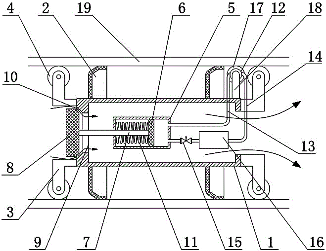
[0020] Such as figure 1 As shown, the hydraulic feedback speed control pipeline robot includes a housing 1 and a leather cup 2, and at least two leather cups 2 are set on the outer wall of the housing 1. The hydraulic feedback speed control pipeline robot also includes a 1 The internal piston device, the regulating valve 8 arranged at one end of the housing 1, the fluid pump 12 and the speed acquisition wheel 17 used to detect the speed of the robot, the housing 1 has an opening 9 on the end surface of one end, the said The piston device includes a piston cylinder 5, a piston 6 and a telescopic rod 7, the piston cylinder 5 is fixed in the housing 1, the piston 6 is slidingly fitted in the piston cylinder 5, and the piston 6 divides the piston cylinder 5 into an oil chamber and an oil chamber. Non-oil chamber, one end of the telescopic rod 7 is fixed to the piston 6 on the side of the non-oil chamber, the other end of the telescopic rod 7 is connected with a regulating valve 8 ...
Embodiment 2
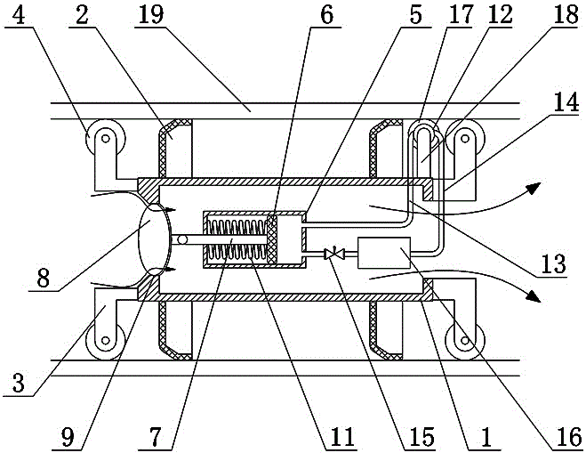
[0025] Such as figure 2 As shown, the hydraulic feedback speed control pipeline robot includes a housing 1 and a leather cup 2, and at least two leather cups 2 are set on the outer wall of the housing 1. The hydraulic feedback speed control pipeline robot also includes a 1 The internal piston device, the regulating valve 8 arranged at one end of the housing 1, the fluid pump 12 and the speed acquisition wheel 17 used to detect the speed of the robot, the housing 1 has an opening 9 on the end surface of one end, the said The piston device includes a piston cylinder 5, a piston 6 and a telescopic rod 7, the piston cylinder 5 is fixed in the housing 1, the piston 6 is slidingly fitted in the piston cylinder 5, and the piston 6 divides the piston cylinder 5 into an oil chamber and an oil chamber. Non-oil chamber, one end of the telescopic rod 7 is fixed to the piston 6 on the side of the non-oil chamber, the other end of the telescopic rod 7 is connected with a regulating valve 8...
Embodiment 3
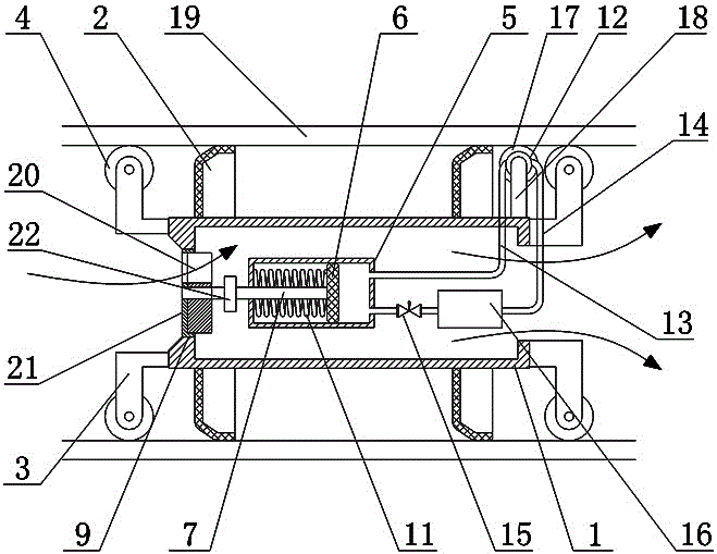
[0030] Such as image 3 As shown, the hydraulic feedback speed control pipeline robot includes a housing 1 and a leather cup 2, and at least two leather cups 2 are set on the outer wall of the housing 1. The hydraulic feedback speed control pipeline robot also includes a 1 The internal piston device, the regulating valve 8 arranged at one end of the housing 1, the fluid pump 12 and the speed acquisition wheel 17 used to detect the speed of the robot, the housing 1 has an opening 9 on the end surface of one end, the said The piston device includes a piston cylinder 5, a piston 6 and a telescopic rod 7, the piston cylinder 5 is fixed in the housing 1, the piston 6 is slidingly fitted in the piston cylinder 5, and the piston 6 divides the piston cylinder 5 into an oil chamber and an oil chamber. Non-oil chamber, one end of the telescopic rod 7 is fixed to the piston 6 on the side of the non-oil chamber, the other end of the telescopic rod 7 is connected with a regulating valve 8 ...
PUM
 Abstract
Description
Claims
Application Information
 - Generate Ideas
- Intellectual Property
- Life Sciences
- Materials
- Tech Scout
- Unparalleled Data Quality
- Higher Quality Content
- 60% Fewer Hallucinations
Browse by: Latest US Patents, China's latest patents, Technical Efficacy Thesaurus, Application Domain, Technology Topic, Popular Technical Reports.
© 2025 PatSnap. All rights reserved.Legal|Privacy policy|Modern Slavery Act Transparency Statement|Sitemap|About US| Contact US: help@patsnap.com